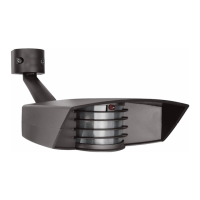
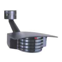
The STEALTH STL110 is an infrared motion sensor designed to automatically turn on lights when it detects movement within its protection zone. It is suitable for outdoor use and can be controlled by a conventional indoor switch or circuit breaker. The device is designed to welcome visitors and deter intruders by activating lights only when needed, making it energy efficient.
Function Description:
The STEALTH STL110's infrared sensor detects small temperature changes caused by the motion of people or cars within its protection zone. Upon detection, it automatically turns on the connected lights. The lights remain on as long as movement is detected within the zone. After the zone is vacated, the lights can be adjusted to stay on for approximately 5 seconds to 12 minutes. The sensor itself consumes only 1 watt of power.
The device offers a "Manual Override Mode" to keep lights on manually at night. This is activated by flipping the indoor switch twice slowly (off-on-off-on) within 2-3 seconds. To return to "Automatic Mode," the switch is flipped once (off-on) within 2 seconds.
The STEALTH STL110 can detect large animals, which can give a property a "lived-in" look. However, animal detection can be limited by turning down the sensitivity knob or by placing opaque weatherproof tape on the lower part of the lens.
Important Technical Specifications:
- Switching Capacity: 8 amps
- Voltage: 120 volts
- Lighting Load (Incandescent/Quartz): 1000 watts
- Lighting Load (Fluorescent): 500 watts
- Detection Pattern: 50' x 110° (standard lens)
- Time Adjustment: 5 seconds to 12 minutes
- Power Consumption: 1 watt
- Surge Protection: I.E.C. specs
- UL Listing: Raintight Photoelectric Switch (CULUS LISTED, suitable for wet locations)
For the STL110-LED model, the lighting load for LED is 300W watts, and the detection pattern is 50' x 100°.
Usage Features:
- Mounting: The STL110 floodlight kits come pre-wired and assembled on the RAB CU4 EZ plate, allowing for mounting on round, rectangular, or octagonal surface or recessed boxes. The sensor can be wall or ceiling mounted.
- Optimal Mounting Height: 6–12 feet high for optimum range and detection.
- Sensor Placement: The sensor should be below and as far as possible away from lights. It functions best when the direction of expected movement is across its detection pattern, not towards the sensor.
- Detection Pattern: The standard lens detection pattern extends out 50 feet and is 110° wide. The sensor can be swiveled in any direction to cover the desired area. Keeping the sensor level ensures full coverage; tilting it down reduces coverage. The STL110 features a "Double Look Down" Lens with one "Look Out" zone and two "Look Down" zones for excellent detection at both long and close range. The Long Range model (STL110LRL) provides a long, narrow protection zone for alleys and along buildings.
- LED Detection Indicator: A red LED above the lens indicates the sensor's logic state. In night-only operation, the LED will be on for daytime detections without turning on lights. At night, the LED is always on, except during detections when the controlled lights turn on. This LED also serves as a deterrent.
- Adjustments (Time, Sensitivity, Photocell):
- Time: Sets how long lights remain on after detection ceases (5 seconds to 12 minutes). Factory setting is 5-8 minutes. Clockwise for more time, counterclockwise for less.
- Sensitivity: Increases or decreases the sensor's responsiveness and range (30% to 100%). Factory setting is 100%. Clockwise for more sensitivity, counterclockwise for less.
- Photocell: Located behind the lens, it controls operation based on ambient light. For night-only operation, turn the knob clockwise to the moon symbol. For 24-hour operation, turn it counterclockwise to the sun & moon symbol. Adjust clockwise for later dusk activation, counterclockwise for earlier activation. Factory setting is Night Only.
- Walk Test: A 5-minute Test Period allows aiming and walk-testing the sensor day or night. During this period, lights stay on for 5 seconds after each detection. To enter Test Mode, turn power off for at least 10 seconds and back on.
- Wiring: The device uses a metal mounting plate, CU4 EZ plate, universal mounting bar, gasket, O-ring gasket, and finishing cap for installation. Power leads and sensor kit leads are brought through holes into the junction box. Ground wires are attached to the grounding screw. Wire nuts are used for connections, secured with electrical tape. Silicone sealant should be used around all openings for a weatherproof seal.
- Switchplate Label: A self-adhesive label with operating instructions is provided to attach to the indoor light switch for quick reference.
Maintenance Features:
- Troubleshooting "Lights Do Not Turn Off":
- Ensure the sensor is not in Manual Override Mode.
- Check for unwanted movement or heat sources (waving branches, water, air conditioners, heating vents, neighboring property). A test can be performed by covering the sensor with a box or bag.
- Ensure the sensor and lights are mounted firmly and do not move.
- Avoid mounting on unstable objects like trees or poles.
- Verify correct wiring; hot wiring can damage circuitry.
- Ensure the sensor is not aimed within 20 feet of a road.
- Ensure heat from lights is not triggering the sensor; sensor should be below and away from lights.
- Troubleshooting "Lights Turn On and Off Inappropriately":
- Ensure the sensor is on its own dedicated circuit, free of motor loads (HVAC, kitchen appliances, garage door openers).
- Avoid wiring multiple sensors in parallel.
- Ensure no people are in the detection pattern during testing.
- Ensure the sensor is below and away from its lights to prevent heat from triggering it.
- Reduce sensitivity if heavy rain, snow, or high winds cause activation.
- Check for white or reflective surfaces close to the sensor that might reflect light back into it.
- Aim the sensor away from reflective objects or move them.
- Self-ballasted PL lamps may cause cycling.
- Reduce sensitivity if moths are attracted to lights and trigger the sensor.
- Troubleshooting "Lights Do Not Turn On":
- Check that lamps and fixtures work, and power is on.
- During daylight installation, remember the 5-minute Test Time. After this, the sensor switches to Automatic Mode and won't work during daylight if the photocell is set to night-only.
- If 24-hour operation is desired, turn the photocell control counterclockwise to the sun and moon symbol.
- Check for other light sources (porch lights, garden lights, streetlights) in the sensor's view that might deactivate the photocell.
- Verify correct wiring.
- Troubleshooting "Lights Turn Off Too Quickly":
- Check if reflected light from the controlled lights or direct light is shining into the photocell, making the unit "think" it's daytime. Adjust the photocell control, move lights/reflectors, or mask the lens.
- Ensure "R" lamps, non-reflector "A" lamps, or self-ballasted PL lamps are not being used in non-enclosed lampholders, as stray light can affect the sensor. Switch to reflector PAR floodlight or Quartz floods.
- Troubleshooting "Range Appears Limited":
- Ensure the sensor is level from side to side and pointed correctly. If tilted, part of the detection zone may be too high.
- Ensure the sensor is not mounted too high (above 20 feet). Optimal mounting is 6-12 feet.
- Ensure movement is across the sensor's pattern, not directly towards it.
- For distant movement not fully within one zone, "Micro Adjust" the sensor by moving it sideways 1/4" to shift zones.
- Troubleshooting "Lights Turn On for Unknown Reasons":
- Mount the sensor in a protected area to reduce false detections from rain, snow, and windstorms.
- Reduce sensitivity if false detections are constant.
- Tilt the sensor lower if it's detecting distant moving objects.
- Check for animals triggering the sensor; create an "Animal Alley" by masking the lower part of the lens.
- Be aware that extreme voltage surges can occasionally activate the sensor.
- Strong local radio signals (CB, Ham, VHF radio transmitters, cellular telephones) can cause "mysterious" activations, but will not permanently damage the sensor.
Limited Warranty:
The STEALTH is covered by a ten-year warranty for defects in workmanship or materials from the date of original purchase. For repair or replacement, the product should be returned freight prepaid and insured, along with the sales receipt and a problem description. Out-of-warranty units or damage unrelated to original manufacture can be repaired or replaced for a fee of $30.00 (made out to RAB Electric). The warranty does not cover incidental or consequential damages, loss of property or revenue, or installation/removal costs.