INSTRUCTIONS
STEALTH STL360 INSTALLATION
RAB Lighting is committed to creating high-quality, aordable, well-designed and energy-ecient LED lighting and controls that make it easy for electricians to install
and end users to save energy. We’d love to hear your comments. Please call the Marketing Department at 888-RAB-1000 or email: marketing@rablighting.com
STL360 KIT ASSEMBLY AND WIRING (cont’d)
Assembly and Wiring.
1. Attach the Universal Mounting Bar with the screws provided
to the junction box. If you are attaching your STL360 kit to
a surface mount weatherproof box, you must use with the
mounting plate with gasket.
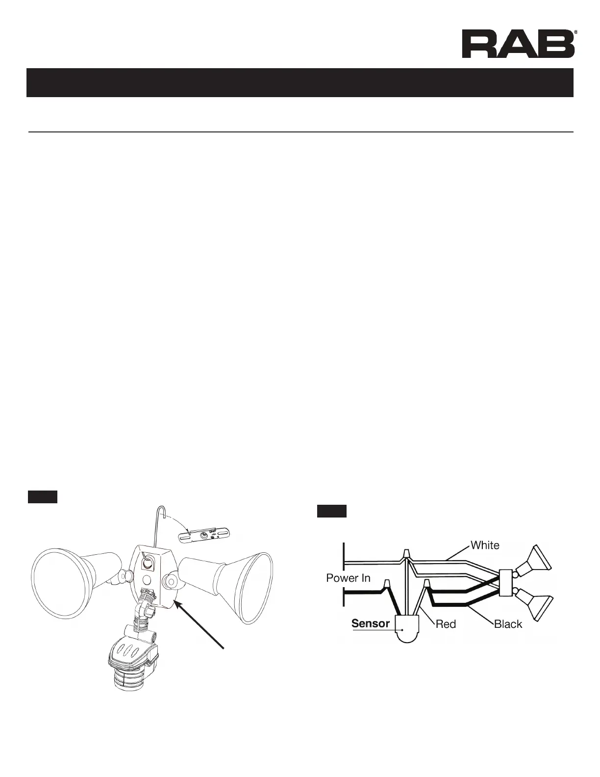
2. Use the “S” shaped Hands Free Hanging Hook (as shown in
Fig 17) to hold the CU4 EZ Plate during wiring.
3. Bring power leads and sensor kit leads through holes in
gasket and plate into junction box.
4. Attach ground wire(s) to junction box grounding screw.
Connect as shown in wiring diagram, Fig. 18.
5. Twist on wire nuts. Secure with electrical tape.
6. Align CU4 EZ Plate and surface plate with gasket (for use with
surface mounted junction boxes) to ensure proper seal. Tighten
CU4 EZ Plate center screw (make sure O-Ring gasket is on the
screw) to attach CU4 EZ Plate to the box.
7. Insert plastic Finishing Cap in the center of the CU4 EZ Plate
for a weatherproof seal.
8. Use silicone sealant around plate and all openings to ensure a
weather proof seal. Seal all unused conduit entries on surface
junction box.
9. Install lamps. Turn on power. Conduct walk test to adjust
sensor response (Fig. 28).
Hood rests in notch
on crossbar
Hands Free
Hanging Hook
CU4 EZ Plate
Fig: 17
Fig: 18
To install STL360 Sensor with separately purchased Floodlights
1. Attach the threaded arm of each oodlight into the RAB CU4
EZ Plate (see diagram, Fig. 17).
2. Screw the threaded arm of the sensor into the bottom hole of
the CU4 EZ Plate. Sensor should be below and as far away from
the oodlights as possible.
3. Attach the Universal Mounting Bar with the screws provided
to the junction box. If you are attaching your STL360 kit to a
surface mount weatherproof box, you must use the mounting
plate with gasket.
4. Use the “S” shaped Hands Free Hanging Hook to hold the CU4
EZ Plate during wiring.
5. Bring power leads and sensor kit leads through holes in gasket
into junction box.
6. Attach ground wire(s) to junction box grounding screw.
7. Position CU4 EZ Plate and surface plate with
gasket (required for mounting on surface junction boxes).
8. Twist on wire nuts. Secure with electrical tape.
9. Make sure all unused openings in CU4 EZ Plate are closed
with plugs (provided).
10. Use silicone sealant around plate and all openings to ensure a
weather proof seal. Seal all unused conduit entries on surface
junction box.
11. Screw in lamps. Turn on power.
12. Conduct walk test to adjust sensor response (Fig. 28).
 Loading...