EasyManua.ls Logo

RAB STEALTH STL360 - User Manual

RAB STEALTH STL360
12 pages
Print Icon
To Next Page IconTo Next Page
Loading...
INSTRUCTIONS
STEALTH STL360 INSTALLATION
RAB Lighting is committed to creating high-quality, aordable, well-designed and energy-ecient LED lighting and controls that make it easy for electricians to install
and end users to save energy. We’d love to hear your comments. Please call the Marketing Department at 888-RAB-1000 or email: marketing@rablighting.com
IMPORTANT
CAUTION: TURN OFF ALL POWER AT CIRCUIT BREAKER/FUSE PANEL.
Read entire Installation Manual before proceeding.
All wiring should comply with local electrical codes and requires a qualied electrician.
The total lighting load connected to STL360 must not exceed (1000W Incandescent, 250VA Standard Ballast
400VA Electronic Ballast (LED).
To switch more wattage, an electrician can install a relay.
Line Carrier Remote Control Systems such as X-10, Leviton or Radio Shack are incompatible with sensors and may
cause false activations.
Do not install sensors on a circuit that feeds motor loads such as kitchen appliances, HVAC equipment, washer/dryer,
or garage door openers.
Sensor functions best when the direction of expected movement is across its detection pattern, not towards the sensor.
Mount 6’-10’ high for optimum range and detection.
WARNING: RISK OF ELECTRICAL SHOCK
Turn o electrical power at fuse or circuit breaker box before wiring xture to the power supply.
Verify that the supply voltage is correct. Connect xture to a 120V, 60 Hz power source.
• Make sure all electrical and grounded connections are in accordance with the National Electrical Code and any applicable
local code requirements.
• All wiring connections should be capped with UL listed wire connectors.
SPECIFICATIONS CONTENTS OF ACCESSORY KIT
STEALTH STL360
Switching Capacity: 8 amps @120V
1000W Incandescent
250VA Standard Ballast
400VA Electronic Ballast (LED)
Voltage: 120V
Protection Pattern: 180° forward
360° below and to the sides
Time Adjustment: 5 seconds to 12 minutes
Power Consumption: 1 watt
Surge protection: 6000 volts
2 Lens Masks
Indoor Switchplate Label
3 Wire Nuts
Adjustment Tool
Mylar Lens Mask
Crossbar with Green
Ground Screw
Hanging Hook
1/2” Close Up Plugs (3)
Slotted Screws (4)
Finishing Cap
O-ring Gasket
Center Mounting Screw
Metal Surface Mounting Plate
with Gasket
Question and Answer IconNeed help?

Do you have a question about the RAB STEALTH STL360 and is the answer not in the manual?

Summary

Important Safety and Installation Notes

Turn Off Power Before Installation

Ensure all power is turned off at the circuit breaker/fuse panel before proceeding with installation.

Electrical Code Compliance

All wiring must comply with local electrical codes and be performed by a qualified electrician.

Load Capacity Limits

Adhere to maximum load limits for incandescent, standard ballast, and electronic ballast loads.

Avoid Motor Load Circuits

Do not install sensors on circuits powering motor loads like HVAC or appliances.

Optimal Sensor Placement Direction

Position the sensor for optimal detection by facing movement across its pattern, not towards it.

Recommended Mounting Height

Mount the sensor between 6' and 10' high for maximum range and detection effectiveness.

Electrical Shock Warning

Turn off power before wiring, verify voltage, and ensure all connections meet codes.

Product Specifications

Switching Capacity

Details the maximum current and wattage the sensor can switch.

Operating Voltage

Specifies the required operating voltage for the sensor.

Detection Pattern

Describes the sensor's forward and downward detection angles.

Time Adjustment Range

Sets the duration lights remain on after detection.

Power Consumption

Indicates the low power usage of the sensor itself.

Surge Protection

Specifies the sensor's protection against voltage surges.

Accessory Kit Contents

Lens Masks

Masks provided to limit or direct the sensor's detection area.

Wire Connectors

Included wire nuts for making electrical connections.

Adjustment Tool

Tool provided for adjusting sensor settings.

Mounting Hardware

Includes mounting plate and gasket for secure installation.

How the Stealth 360 Works

Infrared Motion Detection

The sensor detects temperature changes caused by movement to activate lights.

Dual Sensor Coverage

Combines 180° forward and 360° downward detection for comprehensive coverage.

LED Detection Indicators

Automatic Mode Indicators

Three red LEDs scan continuously in Auto Mode, turning off when lights activate.

Test Mode Indicators

All LEDs are off when the sensor is in Test Mode.

Manual Override Mode Indicators

The middle LED stays on steadily when in Manual Override Mode.

Evening Timer Mode Indicators

The middle LED blinks when the sensor is ready for Evening Timer Mode.

Important Operational Notes

Light Duration Control

Lights stay on during detected movement, with adjustable time-on from 5 seconds to 12 minutes.

Manual Override via Light Switch

Lights can be manually turned on/off at night using the light switch's Manual Override Mode.

Wall Switch Manual Override Function

Flip switch twice (off-on-off-on) within 1-2 seconds to keep lights on.

Evening Timer Function

Flip switch three times (off-on-off-on-off-on) within 1.5-3 seconds to set.

Resuming Automatic Mode

Switch power off for at least 10 seconds, then back on to return to Auto Mode.

Animal Detection and Mitigation

Sensor may detect large animals; adjust sensitivity or use masks to limit detection.

Sensor Adjustment Controls

Using the Adjustment Tool

Use the provided tool or a screwdriver to adjust controls on the sensor's front.

Installation Guide

Choosing the Optimal Location

Select a location where the sensor can see all paths of movement.

Detection Area Coverage

Illustrates the 180° forward and 360° downward detection zones.

Mounting Height Recommendations

Mounting at 6'-10' provides maximum range; higher mounting reduces range.

Handling Difficult Locations

Tips for avoiding false triggers from heat sources or unwanted movement.

Improving Performance in Difficult Areas

Reduce sensitivity or mask the lens to mitigate false triggers.

Ensuring Mounting Stability

Mount the sensor on a stable surface, not on moving objects like trees.

Installation Details

Sensor Placement Relative to Lights

Position the sensor below and away from heat-generating lights to avoid false triggers.

Avoiding Road Interference

Aim sensor away from traffic and maintain a 20-foot safety zone to prevent false triggers.

Improving Performance Near Roads

Reduce sensitivity or mask the lens to prevent detection of passing vehicles.

Mounting Levelness

Mount the sensor level to ensure proper coverage; tilting can affect detection height.

Installation Continued

Optimizing Detection Pattern

Sensor is more sensitive to movement across its pattern; adjust angle/location for best results.

Choosing a Protected Location

Mount in protected areas to minimize false triggers from weather changes.

Kit Assembly and Wiring

General Mounting and Wiring

Instructions for assembling the CU4 EZ Plate and connecting wiring.

Red Pigtail Functionality

The red pigtail is for switching remote or additional fixtures.

Kit Assembly and Wiring Continued

Step-by-Step Assembly and Wiring

Detailed steps for attaching mounting bars, connecting wires, and sealing for weatherproofing.

Installing with Separate Floodlights

Guide for attaching floodlights and sensor to the CU4 EZ Plate.

Adjusting STL360 Settings

Time Setting

Adjusts how long lights remain on after detection, from 5 seconds to 12 minutes.

Photocell Adjustment

Controls operation based on ambient light levels (night-only or day/night).

Sensitivity Adjustment

Adjusts the sensor's responsiveness and detection range.

Evening Timer Functionality

Keeps lights on for 1-8 hours after dusk, offering a 'lived-in' look.

Sensor Modes Explained

Automatic Mode

Lights turn on with movement within the detection zone after dusk.

Evening Timer Mode Operation

Lights stay on for 1-8 hours after dusk, then revert to motion detection.

Test Mode Operation

Allows testing during the day; lights stay on for 5 seconds per detection.

Manual Override Mode

Protected Manual Override

Requires a double-flip of the light switch to keep lights on continuously until dawn.

Resuming Automatic Mode

Switch power off for at least 10 seconds, then back on to reset.

Daytime Manual Override

When photocell is set to day/night, lights remain on continuously if Manual Override is active.

Walk Testing Procedure

Entering Test Mode

Set time to 5s, turn power off for 10s, then back on; wait 30s warm-up.

Performing the Walk Test

Walk across the detection pattern to check coverage and adjust aiming.

Adjusting Sensor Aim

Ensure sensor is level and adjust aiming for desired coverage.

Adjusting Sensitivity and Masking

Modify sensitivity or use lens mask to fine-tune detection area.

Finalizing Settings

Repeat tests, then set time delay and vacating zone for 1 minute.

Troubleshooting Guide

Lights Do Not Turn Off

Check Manual Override, Evening Timer, and obstructions triggering the sensor.

Sensor Triggered by Unwanted Sources

Aim away from movement, mask lens, or lower sensitivity for false triggers.

Sensor on Unstable Mount

Mount the sensor on a stable surface to prevent wind-induced triggers.

Wiring Issues

Check wiring hot status and ensure circuitry is not damaged.

Sensor Aimed Near Road

Maintain a 20ft safety zone and reduce sensitivity to avoid car detection.

Heat From Lights Triggering Sensor

Position sensor below and away from light fixtures.

Lights Turn On;Off Inappropriately

Ensure dedicated circuit, avoid parallel wiring, check for detection by others.

Troubleshooting Continued

Reflective Surfaces Causing Issues

Aim sensor away from reflective objects or lower sensitivity.

Lights Do Not Turn On

Verify lamps, wiring, power, and photocell settings.

External Light Sources

Ensure other light sources are not in the sensor's view.

Advanced Troubleshooting

Lights Turn Off Too Quickly

Check for reflected light tricking the photocell or using non-reflector lamps.

Range Appears Limited

Ensure sensor is level, not too high, and movement is across pattern.

Micro Adjust for Detection

Sideways adjustment can improve detection by crossing zones earlier.

Overview

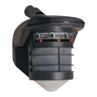
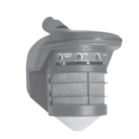
The RAB STEALTH STL360 is an infrared motion sensor designed to automatically turn lights on when it detects temperature changes caused by the movement of people or cars within its protection zone. This device aims to welcome visitors and deter intruders while being energy-efficient.

Function Description

The STL360 utilizes two powerful detectors to provide comprehensive coverage. It offers a 180° long forward range (180° x 60') and superb 360° downward detection, covering all sides and below the sensor. Lights connected to the STL360 remain on as long as movement is detected within the protection zone. Once the zone is vacated, the lights can be adjusted to stay on for approximately 5 seconds up to 12 minutes. The sensor itself consumes only one watt, making it highly energy-efficient as lights are only activated when needed.

The device also features scanning LED detection indicators that serve as a deterrent and show the STL360's current mode of operation.

Usage Features

The STL360 offers several operational modes and adjustment capabilities:

  • Automatic Mode: In this mode, when the STL360 is "On Guard," three red LEDs continuously scan day and night. During detections, the controlled lights will turn on, and the LEDs will turn off. Lights will turn on when movement is detected after dusk.
  • Manual Override Mode: This mode allows users to keep lights on continuously until dawn. To activate, flip the wall switch controlling the sensor twice slowly (off-on-off-on) within 1-2 seconds. If activated during the day, the sensor will enter Manual Override Mode at dusk. The middle LED will be on steady when the sensor is ready for this mode. If set to 24-hour operation (photocell set to MOON/SUN), lights will come on and remain on continuously, but will not turn off at dawn.
  • Evening Timer Mode: This mode keeps lights on for a set duration (1 to 8 hours) after dusk, then reverts to motion-activated mode until dawn. To activate, flip the wall switch three times slowly (off-on-off-on-off-on) within 1½-3 seconds. This can be set during the day, and the Evening Timer Mode will begin at dusk. The middle LED will blink when the sensor is ready for this mode. This feature is useful for evening activities requiring continuous light or to simulate occupancy during vacations.
  • Test Mode: This mode allows for testing the sensor during the day, regardless of the photocell setting. To enter Test Mode, set the time knob to 5 seconds, turn power off for 10 seconds, then back on. After a 30-second warm-up period, the Test Mode starts, during which the lights stay on continuously, and LEDs are off. The sensor will remain in Test Mode until the detection zone is vacated for one minute. During the Test Period, lights will stay on for 5 seconds each time movement is detected.
  • Time Adjustment: The time lights remain on after the detection zone is vacated can be adjusted from approximately 5 seconds to 12 minutes. The factory setting is 12 minutes.
  • Photocell Adjustment: For night-only operation, the photocell knob should be turned completely counterclockwise to the MOON symbol. For 24-hour operation, turn the knob all the way clockwise to the MOON/SUN symbol. Adjusting counterclockwise makes the sensor come on later at dusk, while clockwise makes it come on earlier. The factory setting is Night-only (MOON).
  • Sensitivity Adjustment: The sensitivity knob increases or decreases the responsiveness and range of the sensor, adjustable from 30% to 100%. The factory setting is 100%. This can be used to limit animal detection or to cover a larger area.
  • Resuming Automatic Mode: To return to Automatic Mode from any other mode, switch power off for at least 10 seconds, then back on.

Installation and Placement

The STL360 can be wall or soffit mounted. Optimal mounting height is 6-10 feet above the ground for maximum range. Mounting above 15 feet will reduce the usable range. The sensor functions best when movement is across its detection pattern, not directly towards it.

When installing, ensure the sensor and lights are mounted firmly and do not move when touched. The sensor should be located below and as far away as possible from its lights to prevent heat from the lights from triggering the sensor.

For locations near roads, the sensor should be aimed down so that its maximum range ends at least 20 feet from the road to avoid activation by passing trucks, cars, or air currents. Sensitivity can be reduced, and lens masks can be used to block detection in specific directions.

The sensor should be mounted level from side to side and pointed at the desired coverage area. Tilting the sensor may cause part of the detection zone to be too high.

It is recommended to mount the sensor in a protected area to minimize false activations due to dramatic temperature changes caused by rain, snow, or windstorms.

Wiring and Assembly

STL360 floodlight kits come pre-wired and assembled on the RAB CU4 EZ Plate, suitable for mounting on round, rectangular, or octagonal surface or recessed boxes. A "Hands Free Hanging Hook" is provided to hold the CU4 EZ Plate during wiring.

Multiple sensors can be wired together, but this may complicate troubleshooting. Multiple fixtures can be wired to a single sensor. For loads greater than 1000 watts, a qualified electrician should install a relay.

Maintenance Features

  • Troubleshooting: The manual provides detailed troubleshooting steps for common issues such as lights not turning off, lights turning on and off inappropriately, lights not turning on, and limited range.
  • Lens Masks: Two lens masks are included in the accessory kit. These can be used to block detection in specific directions, which is useful in difficult locations with unwanted movement or heat sources.
  • Adjustment Tool: An adjustment tool is provided to easily adjust the control knobs on the front of the sensor.
  • Weatherproof Seal: The installation process emphasizes ensuring a proper weatherproof seal using gaskets, a finishing cap, and silicone sealant around the plate and all openings. Unused conduit entries on surface junction boxes should also be sealed.

Important Considerations

  • All wiring must comply with local electrical codes and be performed by a qualified electrician.
  • The sensor should not be installed on a circuit that feeds motor loads (e.g., kitchen appliances, HVAC equipment, washer/dryer, garage door openers) as this can cause false activations or sensor malfunction due to significant voltage variations.
  • Line Carrier Remote Control Systems (e.g., X-10, Leviton, Radio Shack) are incompatible with the sensor and may cause false activations.
  • The sensor should be mounted on a stable surface, not on objects that move in the wind, such as trees or poles.
  • For optimal performance, ensure lights are not reflecting back into the sensor or shining directly into the photocell, as this can cause the unit to turn off prematurely, "thinking" it is daytime. If using non-reflector lamps, consider switching to reflector PAR floodlight lamps.

RAB STEALTH STL360 Specifications

General IconGeneral
Coverage360°
Time Adjustment5 seconds to 12 minutes
Sensitivity AdjustmentAdjustable
Protection RatingIP54
Output TypeRelay
MaterialPolycarbonate
MountingCeiling or Wall
Operating Voltage120V AC
Operating Temperature-20°C to +50°C
Wattage1000W incandescent, 500W fluorescent

Related product manuals