5
3. If port sleeve is seized in liner (013 68), tap it
radially using piece of hard wood located in
actuator slot. Do not damage or distort port
sleeve.
4. The liner can normally be cleaned in position. If
necessary, unscrew liner retaining screw (610
01) and prise liner from base.
Cleaning/Replacement of Parts
5. Parts can be cleaned using a proprietary scale
solvent. Do not use abrasives or acid solutions.
6. Check joints and seals, including liner '0' seals,
if liner removed.
7. When ordering spares, please state type of
mixing valve for which they are required, the
part names and their numbers.
Parts List
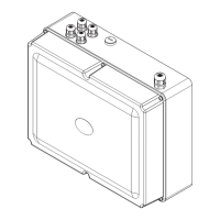
001 66 Cover
003 66 Base
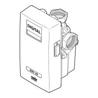
045 88 Nameplate
050 66 Spring
110 66 Stop plate
111 66 Fouling plate
190 06 Body
195 06 Clack facing (water)
195 10 Clack facing (steam)
196 06 Cap
610 01 Screw - liner
610 01 Screw - fouling plate
610 09 Screw - stop plate (3)
610 11 Screw - blanking
610 51 Screw - cover (8)
610 91 Screw
612 87 Screw - nameplate (2)
620 11 Acorn nut
630 82 Seal - liner centre or bottom (2)
630 85 Seal - liner top
634 31 Cap gasket
639 68 Washer
639 98 Washer
641 20 Seal - spindle
901 66 Thermostat assembly
909 06 Clack assembly - water
909 10 Clack assembly - steam
916 66 Temperature regulating handle
assembly
925 70 Liner and sleeve assembly
1152 002 Cover joint
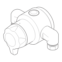
Check Valves
Check valves will not operate satisfactorily if
deposits form on seats or if seats become damaged.
Hot water or steam entering cold supply or vice versa
indicates service is necessary.
To service check valves, first isolate supplies.
Remove cap (196 06). Clean seat using a proprietary
scale solvent. Slight damage to seats can usually be
lapped out, otherwise check valve must be replaced.
Examine clack assembly (909 06) or 909 10) and if
damaged replace.
Check cap gasket (634 31) is in good condition.
Should you experience a problem not covered by
these instructions, our advice should be sought.
Re-Assembling
8. If liner removed, smear '0' seals with petroleum
jelly to assist entry of liner into base. It will
probably be necessary to tap liner into position
using soft faced mallet.
9. Re-assemble thermostat assembly into cover
and tighten stop plate screws but do not over
tighten.
10. Check cover joint (1152 002) is in position, then
re-assemble cover to base, ensuring lug of
thermostat assembly actuator engages in slot at
top of port sleeve. Refit cover screws.
11. Reset maximum temperature as earlier
described.
 Loading...