Installation Manual
Combi - cod. 99943NA – November 2002
15
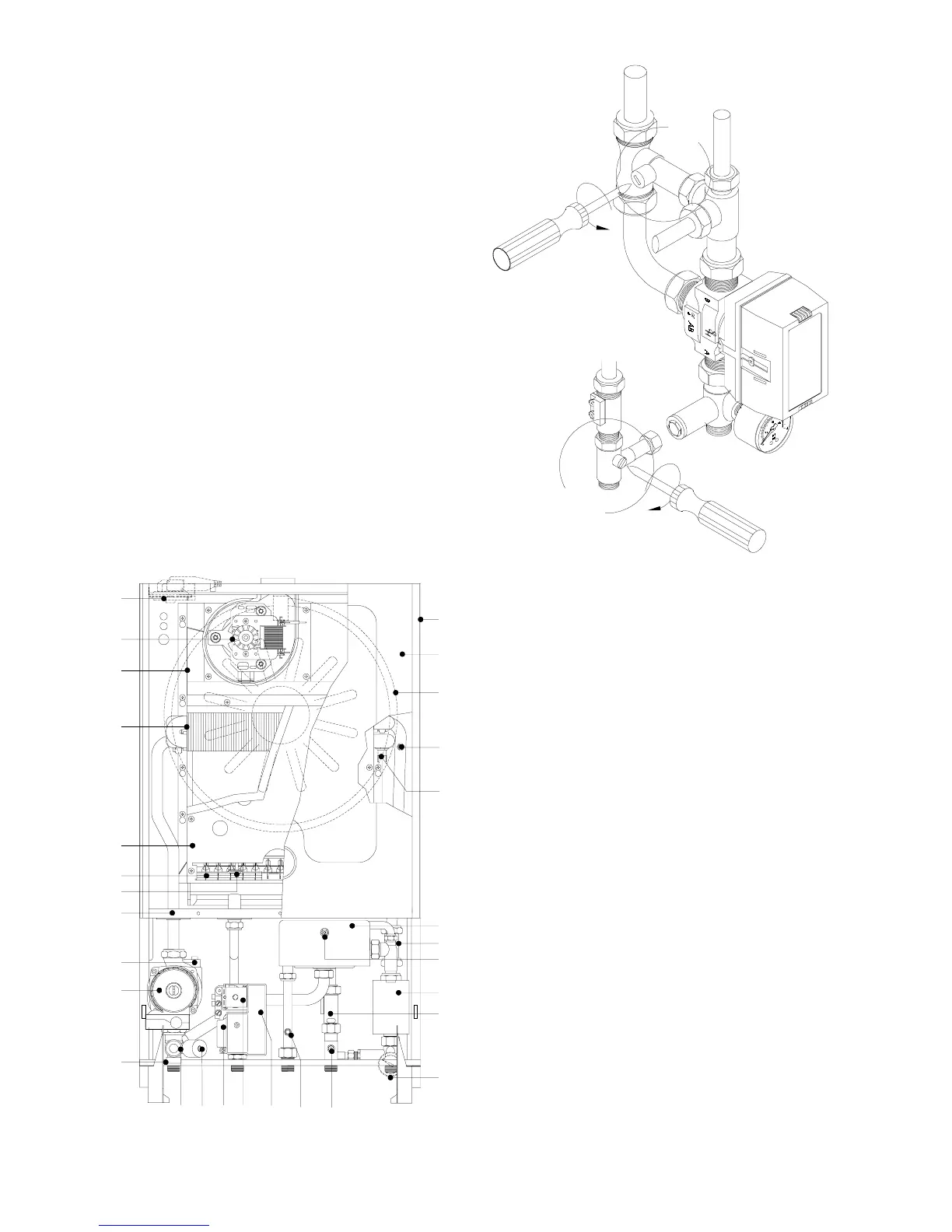
BY-PASS
All boilers are fitted with a by-pass. This element is
essential in the following cases:
• if a two-way zone valve is installed
• if thermostat valves are installed in the radiators.
To adjust the by-pass proceed as follows (see fig.1
pos.A):
fit the screwdriver to the plastic screw of the by-pass,
bearing in mind that when the slot of the screw is
horizontal the by-pass is totally open, allowing all the
water to pass, while when it is vertical the by-pass is
totally closed. For partial by-pass flows, use the
adjuster screw.
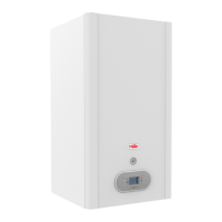
MAIN COMPONENTS
mod. RSF 20 E - RSF 24 E
KEY
1. FRAME
2. FLUE HOOD – ROOM SEALED COMBUSTION CHAMBER
3. COMBUSTION CHAMBER
4. ROOM SEALED CHAMBER COVER
5. ROOM SEALED CHAMBER BACK
6. HEAT EXCHANGER Mod. 20.000
HEAT EXCHANGER Mod. 24.000
7. D.H.W. EXCHANGER H20-H20 PB 21-73
D.H.W. EXCHANGER H20-H20 PB 24-73
8. EXCHANGER AIR VENT VALVE
9. MULTIGAS BURNER WITH 13 RAMPS
10. IGNITION ELECTRODE
11. FLAME IONISATION ELECTRODE
12. HEATING SAFETY THERMOSTAT
13. ELECTRONIC GAS VALVE VK4105 A 1001
14. GAS PRESSURE MODULATOR
15. ELECTRONIC IGNITION BOARD
16. EXPANSION VESSEL
17. 3-SPEED CIRCULATION PUMP WITH AIR VENT
18. AUTOMATIC AIR VENT
19. HEATING CIRCUIT 3 bar PRESSURE RELIEF VALVE
20. DRAINING TAP
21. WATER PRESSURE GAUGE
22. WATER PRESSURE SWITCH
23. HEATING SENSOR
24. HOT WATER SENSOR
25. 3-WAY DIVERTER VALVE
26. FLOWSWITCH CONNECTION WITH FLOW LIMITER
27. ELECTRONIC FLOWSWITCH
28. BY-PASS
29. AIR PRESSURE SWITCH
30.
FAN
20
13
19 23
14
15
24
26
20
18
17
5
9
11
3
6
2
29
30
4
8
27
25
28
7
12
24
16
1
A
B
C
Fig. 1
Fig. 2