Installation Manual
TECHNICAL DATA
Type C unit
Type C devices are devices in which the combustion circuit (air intake,
combustion chamber, exchanger, combustion exhaust) is sealed off
from the place where they are installed.
Coaxial vertical
Coaxial horizontal
C32
C12
C52 Double
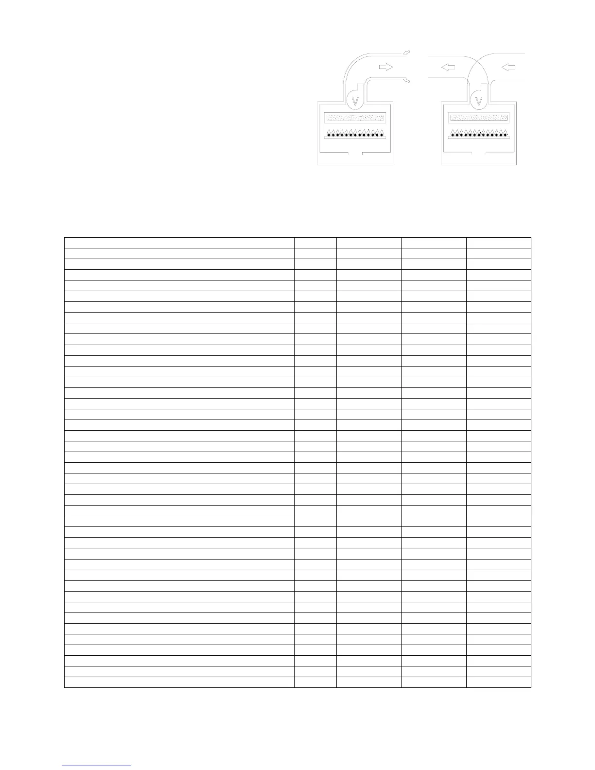
MODELS RSF 20 E RSF 24 E RSF 30 E
Maximum rated input kcal/h 22016 25628 29670
kW 25.60 29.80 34.50
Btu/hr 87398 101737 117783
Minimum rated input kcal/h 10320 15050 16340
kW 12 17.5 19
Btu/hr 40968 59745 64866
Maximum rated output kcal/h 20387 23475 27445
kW 23.71 27.30 31.91
Btu/hr 80931 93191 108949
Minimum rated output kcal/h 9030 13191 14559
kW 10.50 15.34 16.93
Btu/hr 35847 52366 57796
Heating temperature adjustment °C 30-80 30-80 30-80
Max. working pressure (heating) bar 3 3 3
Min. working pressure (heating) bar 0.3 0.3 0.3
Expansion vessel capacity (initial pressure 1 bar) litres 10 10 10
Continuous hot water drawing with Dt 30° litres/min 11.33 13.04 15.25
Max. working pressure (water) bar 6 6 6
Min. working pressure (water) bar 0.3 0.3 0.3
Width mm. 410 450 450
Height mm. 800 800 800
Depth mm. 270 320 320
Weight kg. 42 47 50
Coaxial exhaust flue diameter kit A (max. flue lenght) Ø (m) 100/60 (3) 100/60 (3) -
Coaxial exhaust flue diameter kit G (max. flue lenght) Ø (m) - - 125/80 (3)
Double exhaust flue diameter kit B (max. flue lenght) Ø (m) 80/80 (30) 80/80 (30) 80/80 (30)
Double exhaust flue diameter kit C (max. flue lenght) Ø (m) 118/80 (3) 118/80 (3) 118/80 (3)
Flow/return connections Ø 3/4” - 3/4” 3/4” - 3/4” 3/4” - 3/4”
Cold water connections Ø 1/2” 1/2” 1/2”
Hot water connections Ø 1/2” 1/2” 1/2”
Gas connections Ø 1/2” 1/2” 1/2”
Electrical connection 50 Hz V 230 230 230
Power supply W 170 170 170
Electrical protection IP X4D X4D X4D
Nox class II I II
Burner jets NP 11 G20 Ø 1.30 - -
Burner jets NP 11 G30/31 Ø 0.78 - -
Burner jets NP 13 G20 Ø - 1.25 -
Burner jets NP 13 G30/31 Ø - 0.77 -
Burner jets NP 17 G20 Ø - - 1.20
Burner jets NP 17 G30/31 Ø - - 0.75
DOMESTIC HOT WATER WITH STORAGE CYLINDER – TA05A027.A0504
4
 Loading...