D279A Operation & Installation Manual
Copyright © 2000 Radionics Page 9 46456B
D279A
Installation
3.0 Installation
You can mount the D279A directly onto a wall, install it in a flush-mount unit, or attach it to a D55 Desk Stand (see
the special installation instruction sheet that comes with each item). Do not mount the D279A in a location exposed
to direct sunlight. Direct sunlight makes the LEDs less visible, and intense heat can damage the D279A enclosure
and electrical components.
Wiring between the D279A and the panel is not supervised:
The wiring between the D279A and the panel is not
supervised for trouble conditions. Wiring between the D279A and remote sensing devices is supervised with end-
of-line resistors.
3.1 Connecting the D279A to the Panel
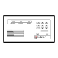
TOP COVER TABS
TOP TAB SLOTS
MOUNTING HOLE
BOTTOM TAB SLOTS
MOUNTING HOLE
MOUNTING HOLE
MOUNTING HOLE
ENCLOSURE COVER (BACK VIEW)
BOTTOM COVER TABS
(WITH COVER REMOVED)
(WITH COVER ATTACHED)
Figure 1: Installing the D279A
1. Remove the front cover from the enclosure base (see Figure 1 above). Use a small flat-blade screwdriver to
gently push the two bottom cover tabs back. As the tabs are pushed back, lift the bottom of the cover away from
the base. Remove the cover.
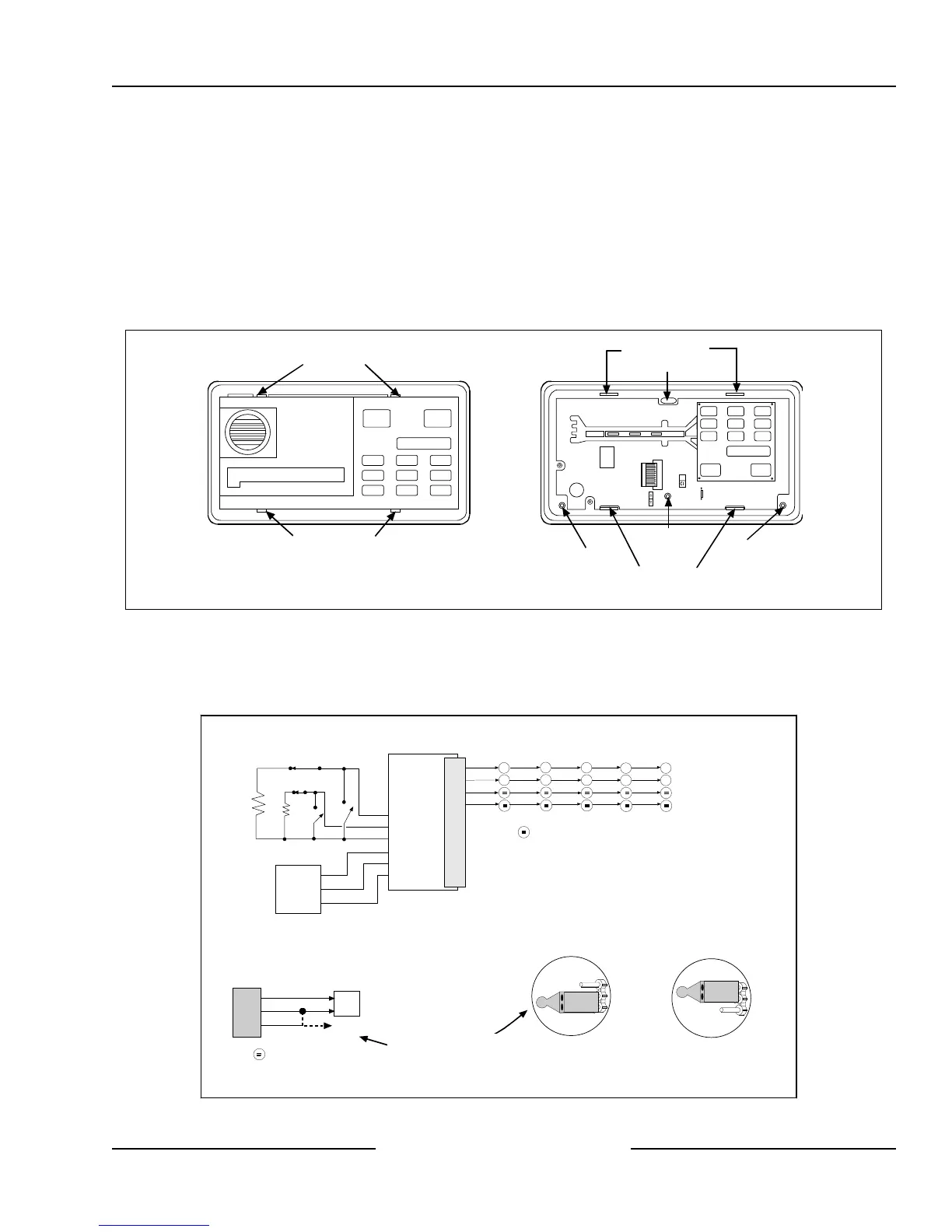
Figure 2: Wiring the D279A
Circled numbers represent
terminals on control panel
J4 JUMPER POSITION
FOR SINGLE ZONE CONNECTION
For single zone connection:
2
3
4
J4 JUMPER POSITION
FOR MULTIPLE ZONE CONNECTION*
For single point connection,
use this jumper position
Install into 1 k
Ω
terminating loop input.
7
3
D6112 D7112 D8112
3
4
D279A PINOUTS
+12 VDC
COMMON
BURGLARY
PAN IC
DELAY
INSTANT
RELAY COMMON
10
9
8
7
6
5
4
3
2
1
COMMON
NO RELAY CONTACT
NC RELAY CONTACT
D4112
YELLOW
AUX POWER
OPTIONAL
ANNUNCIATION
DEVICE
WHITE
1k
Ω
EOL
RESISTOR
1k
Ω
EOL
RESISTOR
FUNCTION
EARTH GROUND
PROTECTIVE
ZONE OR
ON-BOARD
POINT
BLUE
BLACK
VIOLET
BROWN
ORANGE
5
11
3
4
GREEN
BLACK
RED
D7212/D9112
3
9
D279A PINOUTS
COMM
POINT
BLACK
GREEN
YELLOW
EARTH GROUND
PROTECTIVE
ZONE OR
ON-BOARD
POINT
Install into 1 k
Ω
terminating loop input.
CAN TIE INTO A SHARED
POINT OR OWN POINT