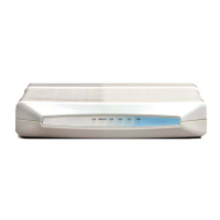
Connecting power to the IDU Chapter 3
RADWIN 2000 User Manual Release 2.6.40 3-11
To mount an IDU-C:
1. Attach the rack mounting brackets (K) to the IDU.
2. Bolt the IDU into an empty slot in the rack, ensuring that it sits securely.
3. Ground the IDU to the rack using grounding lug I. The IDU should be left perma-
nently grounded.
Connecting power to the IDU
The IDU-C has redundant power connection circuits (items G and H in Figure 3-11 above).
An enlarged schematic of the power connectors is shown in below:
STBY
Hot Standby Mode - for use with
Trunks only
Link State
Green
Blinking Green
Red
Orange
Off
Primary
Secondary
Primary
Secondary
Off
Active
Not active
Not active
Active
HSM not activated
Hot Standby Mode - For use with
Ethernet only in a 1+1 Ring
application)
Link State
Green
Blinking Green
Red
Orange
Off
Hardware ready
Table 3-3: IDU-C and New Style IDU-E Front Panel LEDs for HSS
Color Function
Green This ODU is HSS master, generating signal, and HSS Sync is OK
Blinking
Green
This ODU is a HSS client and in Sync
Red HSS not operational due to improper signal detection. This ODU is not transmitting
Orange
HSS is operational. One of the following conditions apply:
• This ODU is a master that is generating signals and detecting signals
• This ODU is a master that is generating signals but detected improper signals
• This ODU is a client “Continue Tx” but is not detecting signals
• This ODU is a client “Disable Tx” and is detecting signals from multiple sources
All orange cases transmit.
Off
HSS is not activated
Disconnection between ODU and IDU
Note
Instead of using the rack mounting brackets, the IDU may be rail mounted
using the four screw holes on each of its sides.
Table 3-2: IDU-C Front Panel LEDs (Continued)
Name Color Function

 Loading...