www.raisecom.com User Manual
5
Chapter 5 Installation
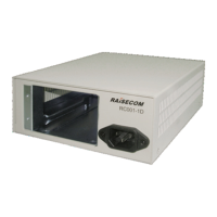
1. Fix a service module into RC001-1D and tighten the screws on the service module.
2. When adopting AC power supply, please connect one end of the power supply cable to the
power supply module on the front panel of RC001-1D and the other end to the power supply.
When adopting DC power supply, please correctly connect the power supply cable and ground
cable and then turn on the air switch.
3. Please check whether the power supply cable is well earthed and make sure that protection earth
is well connected with the grounding system.
Service modules that work in RC001-1D:
Product Category Description
RC9xx series interface converter Ethernet to E1 modular interface converters
RC954-FE(FX)4E1
RC954-2FE4E1-BL
RC954-2FE8E1-BL
RC8xx series fiber optic multiplexer Modular PDH multiplexer with 4 or 8 lines of
E1 service
RC832-120L
RC832-240L(-BL)
RCMS2xxx series multi-service
PDH multiplexer
Modular multi-service access device with 4 or 8
lines of E1 service and 1 line of FE or GE
service
RCMS2802-120LFE(-BL)
RCMS2802-240LFE(-BL)
RCMS2802-120LGE(-BL)
RCMS2802-240LGE(-BL)
 Loading...