OIM‐600056 Rev.0 12
resume operation, twist the red E‐Stop Button and allow the
actuatortore‐settotheupposition.
Overload Shut‐Off Valve (Optional) – The local control valve is
equipped with an overload shut‐off valve.The valve senses the
differential air pressure delivered to
the air motor and is
calibratedatthefactorytolimitthemaximumlinepullto160%of
therated line pullona givenlayer.If anoverload conditioned is
experienced, the reset button will receive a signal causing the
brake(s) to set and the inhaul direction of travel
will stop.In
order to continue operation, the operator will need to allow the
controlhandletoreturntoneutral,depresstheresetbutton,and
slowly begin to move the main control lever in the payout
directiontoremovetheexcessload.Excessivelyjerkingthemain
controllever inthe inhaul
direction can causethe overload shut‐
off valve to actuate just as if an overload condition was
experienced.Reset the button and continue operation with
smoothoperationofthecontrolhandle.
For information on Checking and Resetting the Overload
Shut‐OffValverefertoSection5.
Proper testing
and adjustment of Overload Shut‐Off Valve
shouldonlybeperformedbyaRamWinchandHoisttrained
technician.
4.3. ManualBandBrake(Optional)
The winch may be equipped with a secondary manually applied
and released drum brake.This brake is intended to serve as a
back‐upbrakeandaparkingbrake.Pressingtheredbrakehandle
down will increase the holding power of the brake.The brake
handle has a break over cam
mechanism that serves to lock the
brakeinthefullyon position.Duringoperation,thebrakehandle
shouldbeallthewayupandforward.
4.4. AutomaticDrumBandBrake
The automatic drum brake engagesthe machined surface on the
winch cable drum directly.The brake is spring set, with a
compressionspringlocated insidethebrakereleasecylinder,and
isairpressurereleased.Theairsignaltoreleasethebrakeissent
from the control valve once the operator begins
to move the
Winch Control Lever away from the neutral position.Once the
Winch Control Lever is returned to neutral, air in the cylinder is
ventedandallows the springtoautomaticallysetthebrake.The
brake needs to be properly adjusted to hold the required load
(seeSect.5.8).
4.5. AutomaticDiscBrake
The automatic disc brake is a spring applied, air released brake.
Using an air actuated, spring loaded piston, the brake
automatically disengages when motor is operated and engages
whentheWinchControlLeverisreturnedtotheneutralposition.
Air pressure ported through the brake housing overcomes spring
pressure and moves
the piston which releases the brake.When
the Winch Control Lever is placed in the neutral position, air is
vented,springpressureovercomesairpressureandspring
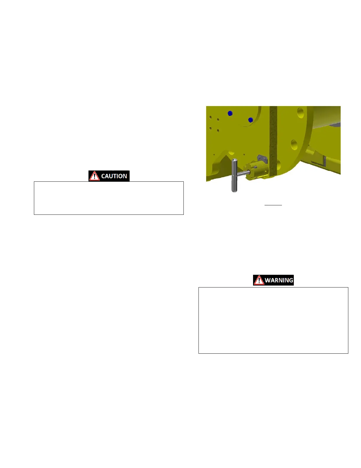
4.6. DrumLockPin(Optional)
TheDrumLockingPin system consistsofaspring loaded pin that
engageswithholesmachinedintotheoutboarddrumflange(see
Figure 8).The locking pin can be used to mechanically hold the
full rated load and should be used if the load must be left
suspendedforlongperiods
oftime.
ToEngageDrumLockingPin:
WhenfacingtheDrumLocking Pin, pullthe T‐handletoward you
and turn ¼ turn clockwise to unlatch the pin from the retracted
position and allowthe pinto engage.If thepin does notline up
with a hole in the
flange, slowlyoperate the winch to rotate the
drum in the necessary direction and the spring will push the pin
intothelockingholeasitrotatesintoposition.
Always visually inspect that the pin is fully locked in the
engagedposition.
Before disengaging the locking pin, ensure
that all braking
mechanismsare engaged and that all personnel are clear of
thesuspendedloadorthetensionedwirerope.
If locking pin does not easily disengage, it is an indication
that the load is held by the locking pin.Slowly operate the
winchintheinhauldirectiontoremoveloadfrom thelocking
pin and confirm that the suspended load is held by the load
brakes.
ToDisengageDrumLockingPin:
WhenfacingtheDrumLocking Pin, pullthe T‐handletoward you
to the fully retracted position and turn ¼ turn counter‐clockwise
tolatchthepinintheretractedposition.
4.7. RotaryLimitSwitch(Optional)
The rotary limit switch, located on the winch frame opposite the
motor, can be adjusted to limit travelof the winch drum in both
the Inhaul and Payout directions.As the drum rotates, cams
within the limit switch will acti vate a valve that, when tripped,
signalstheresetbutton(seeFigure
7)toshutdown thewinchand
Figure8
 Loading...