OIM‐600056 Rev.0 11
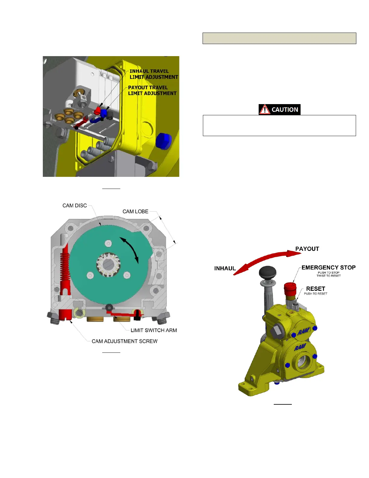
position by adjusting the Payout Travel Limit Adjustment Screw
(showninBLUE).
3.10. TouchUpandCleanUp
After the initial Start‐Up, thoroughly clean the machinery to
removeanyoilspills,excessivegrease,dirtanddebris.Performa
finalinspectionforanysignsofleaks,thatallguardsareproperly
inplace,andthatallfastenersareproperlytightened.Repairany
paint that may have become damaged during
the installation
process.There may also be a commission acceptance test
required for this machinery prior to putting into service.Check
withyoursupervisor.
4. Operation
4.1. Controls
ControloftheRamR7Pis handled via the localcontrolhandleat
thewinch.Thelocalcontrolvalve(seeFigure7)isequippedwith
a lift to unlatch neutral safety lock‐out to prevent inadvertent
actuation of the control.In addition, the local control valve is
equippedwithared
EmergencyStoppush‐button(pushtostop/
twisttoreset).Aswellasaresetbutton.
Neverleavethewinchunattendedwithtensionontheline.
Never operate the winch without means to visually monitor
theequipment.
4.2. LocalControls
WinchControlLever‐Themaincontrollevercontrolsthespeed
anddirectionofthewinchdrum.Thefurtherthevalvehandleis
displacedfromthecenterpositionthefasterthewinchdrumwill
turn.Pullingthelevertowardtheoperatorwillcausethewinch
drumtoturncounter‐clockwise(viewedfrommotorend)to
retrievethewirerope.Pushingtheleverawayfromtheoperator
willcausethewinchdrumtoturnclockwise(viewedfrommotor
end)topayoutthewirerope.Thebrakesautomaticallyrelease
whenthecontrolhandleismovedawayfromcenterandsets
oncethehandleis
returnedtocenter.TheWinchControlLever
springreturnstoneutralandisequippedwithalifttounlatch
neutralsafetylock‐outtopreventinadvertentactuation.Avoid
suddenmovementsofthelevertoensuresmoothoperationof
thewinch.
Emergency Stop – The emergencystop button, when depressed,
shutsoffairsupplytothemaincontrolvalvecausingthemotorto
stop turning and immediately sets the Automatic Brake(s).To
Figure5
Figure6
Figure7
 Loading...