OIM‐600056 Rev.0 10
Figure4
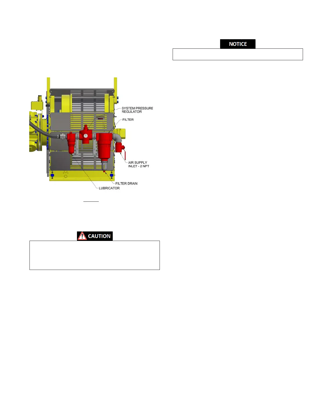
3.6. AirSupplyConnections
Thewinchissuppliedwitha filter,inletairpressureregulator,and
an air supply lubricator (see Figure 4).Connect the air supply to
the2NPTfilterinlet.RefertothePneumaticSchematic(Dwg.No
409564)inSection5foradditionalinformation.
The air supply line coming to the winch
should be as large as
possible, recommended no smaller than 2 in., to minimize
pressurelosses.The airsupply shouldbecleananddry.
Lubricator must be located no more than 10ft (3m) from
motor.
Shutoffairsupplybeforefillingairlinelubricatororservicing
thefilter.
Donotadjusttheregulatorabove90psi(6.2Bar).
3.7. Exhaust
Theairmotorandthecontrolvalveexhaustrequireafreeflowof
exhaust air during operation.Restriction to exhaust air will
reducetheperformance ofthewinch.Thecontrolvalve hasa1‐
1/2 NPT connection and the motor has a 2‐1/2 NPT exhaust
connection.Installanappropriatelysized
highqualityairmuffler
ineachport toproperlyattenuatethesoundleveloftheexhaust
air.Temporaryplugsareinstalledintheseportsatthefactoryfor
shipping purposes.These plugs must be removed before
operatingwinch.
3.8. InitialStartUp
After following the instructions given in Sections 3.1 thru 3.7 of
this manual but prior to putting the winch into service, it is
advisabletoconductthefollowingcontrolchecks.
Read and understand the Section 4 of this manual before
performingthefollowing
i. Inletpressureregulatorsetat90psi(6.2Bar).
ii. Setlubricatorat13dropsperminuteandrunfor5to10
minutesto ensurefull lubrication and then reduce to 8
to10dropsperminute.
iii. Pull the control handle slowlytoward the operator and
notice
thatthedrumrotatesinthe“INHAUL”direction.
Notethat the control leverhas a lifttoun‐latch feature
inthecenterposition.
iv. Verifythatthespeedofthedrumisproportionaltothe
displacementofthecontrolhandleandstartsandstops
smoothly.
v. Allow the control handle
to snap back to the center
position and verify that the winch drum comes to an
abruptstopandthebrakesets.
vi. Repeatstepsiii.thruv.forthe“PAYOUT”direction.
vii. Depress the E‐Stop button and verify that the winch
drum does not rotate and the brakes
do not release
when the control handle is displaced from the center
position.RotatetheE‐Stopknob toreset.
viii. Take note ofanynoiseor unusual vibrations.This may
be an indication of improper installation (ie. Out of
toleranceflatnesstothemountingsurface).
3.9. RotaryLimitSwitch(Optional)
Once the wire rope has been spooled onto the drum and the
reevingof the lifting system hasbeen set, the rotary limit switch
canbecalibrated.
The rotary limit switch has two sets of cam discs that turn with
thecabledrum.One camdisc controlstheInhaultravellimit
and
thesecondcamdisccontrolsthePayouttravellimit.Asthelobe
on the cam disc comes around it actuates the limit switch valve.
Thepositionofthelobecan beadjustedwithrespecttothelimit
switchbyturningthecamadjustmentscrew(seeFigures5and6).
Tobegincalibratingtherotarylimitswitch,loosenthe4screwsto
removethebackcover(asshowninFigure5).Runthewinchuntil
theuppertravelpositionisreached.Usingascrewdriveror4mm
hexkey,turntheInhaulTravelLimitAdjustmentScrew(shownin
RED in Figure
5) to advance the cam lobe until you see the limit
switch arm begin to move and then advance the screw 1
additional turn (see Figure 6).Then run winch in the Payout
direction for 2 rotations of the drum to allow the limit switch
valvetoreset.Now,Inhaul
towardtheuppertravelpositionand
allow the limit switch valve to activate and shut down travel.
Press the reset valve as required, and continue to advance or
retardthecamasnecessaryuntilthetrippointlocationhasbeen
achieved.Repeat the same operation for the lower travel
 Loading...