OIM‐600056 Rev.0 8
3. Installation
The design of the mounting structure for the winch should take
intoaccounttheweightoftheunit,additionalvesselaccelerations
and angles, as well as applied line pulls.Consult a structural
engineer.
The Ram R7P is designed to be mounted with the provided bolt
pattern directly to the customer’s rigid steel structure. Ram
recommendsusingstructural grade fastenersASTMA490,orSAE
Grade8orbetter.RefertoSection3.2forInstallationTolerances
forflatnessandotherdimensionalparameters.Theprovidedbolt
pattern is given on drawing S001960 located in Section 5 of this
manual.
Avoid welding on the frame of the winch.If welding must be
done, limit it to the frame only and position the ground clamp
close to where the welding is to occur.Take every precaution to
not
arc the bearing or over‐heat shaft seals.Protect hoses from
sparks and excessive heat.Care should be taken to not allow an
electricarctopassthroughthewirerope.
Ifweldinghastobedonetothewinchframe,pleasenote thatthe
Ramwinchframeisconstructedof anAWSGroupIand/orGroup
II material.Always use a qualified weld procedure and certified
personnel.Always abide by safety procedures established and
governedby yourspecific area of
operation.Make sure the area
issafebeforebeginninganyweldingprocedures.
Prior to installation, carefully inspect the unit for any signs of
damage that may have occurred during shipping.Before
operation, verify oil levels and correct if necessary.Refer to the
Lubricationsectionofthismanualforrecommendations.
3.1. ShippingandHandling
Lifting of equipment should only be conduct ed by skilled and
properlytrainedandauthorizedpersonnel.Onlyusecertifiedan d
properlysizedriggingequipment.Keepallpersonnelclearoflifted
items.
TypicallythewinchisshippedfromtheRamfactoryonawooden
palletthatisintendedforhandlingthewinchwithaforklift.This
pallet should not be used for overhead lifting where slings are
wrappedunderthroughtheforkliftpockets.
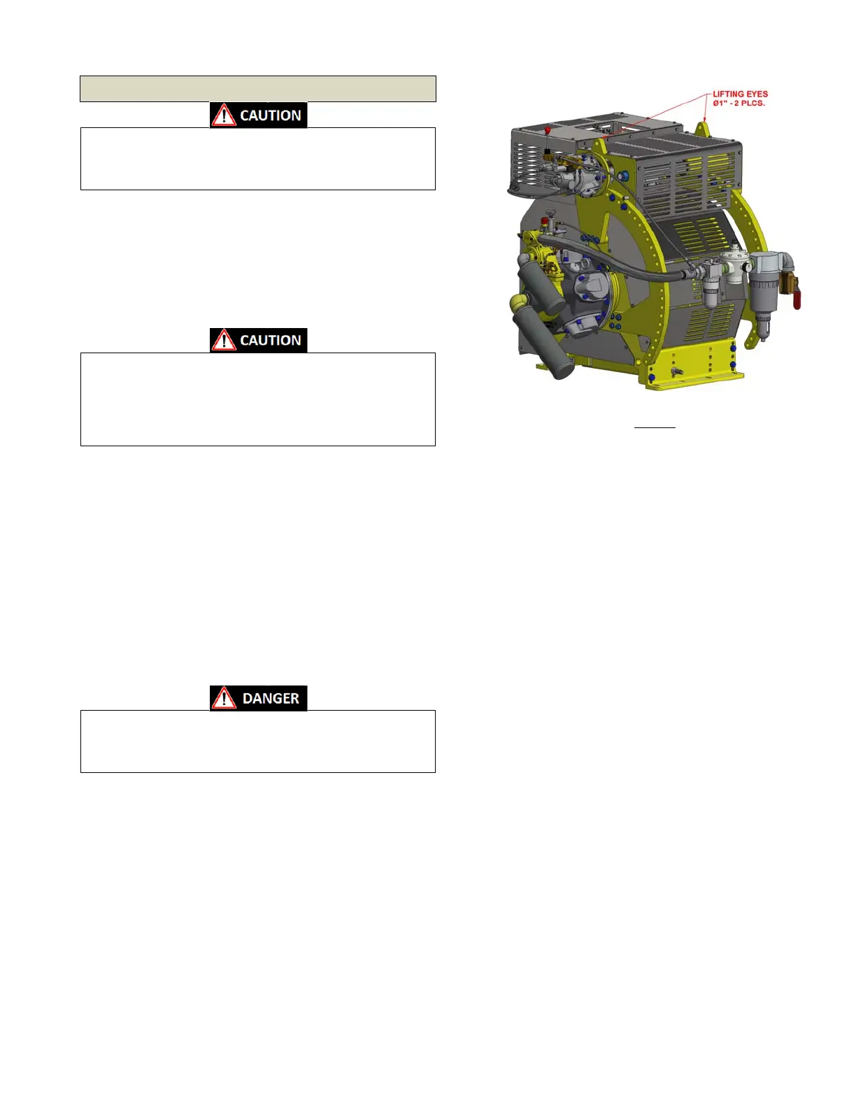
When lifting the winch into position for
final mounting, it is
recommendedthattheprovidedliftingeyes(qty.2)onthewinch
framebeutilized(seeFigure1).
Use a 3/4 in. shackle to provide sufficient throat depth in the
shackle for lifting sling clearance.After placing the winch into
position and removing the shackles.Note: details may
vary by
model,anddrumguardconfiguration.
3.2. InstallationTolerances
Once the Winch is set into position, check the mounting surface
forflatness.Themountingsurfaceshouldbeflatandlevelwithin
0.06in. (1.5mm).If necessary, shim under each mounting bolt
hole location to ensure that the frame sits flat, level, and is
properlysupported.
Use 7/8inch (22 mm) Grade 8
or ASTM A490 or better mounting
hardware and use with lock washers, and hex nuts of similar
grade.LubricatethethreadsoftheboltswithAnti‐Seizeorsimilar
andtorqueevenlyto394ft*lbs.(534N*m).
3.3. WireRope
Theminimumrecommendedropesizeforthiswinchis7/8in.(22
mm).Whenselectingtherequirementsforthewireropeforyour
particular application it is important that you maintain a proper
safety factor as well as selecting proper wire rope construction
type,directionoflay,protectivecoating,etc.Consult
areputable
wire rope manufacturer or distributor for assistance in the
selection.
Other considerations for the wire rope are the size of turning
sheavesanddirectionoftheturnsintherope.Maintainaproper
pitch diameter to wire rope diameter ratio as bending rope too
tightlyreducesthestrength
oftheropeanddecreasestheservice
life.Back bending the rope, bending the rope in a direction
opposite of how it is wrapped on the drum should be avoided if
possible.
Figure1
 Loading...