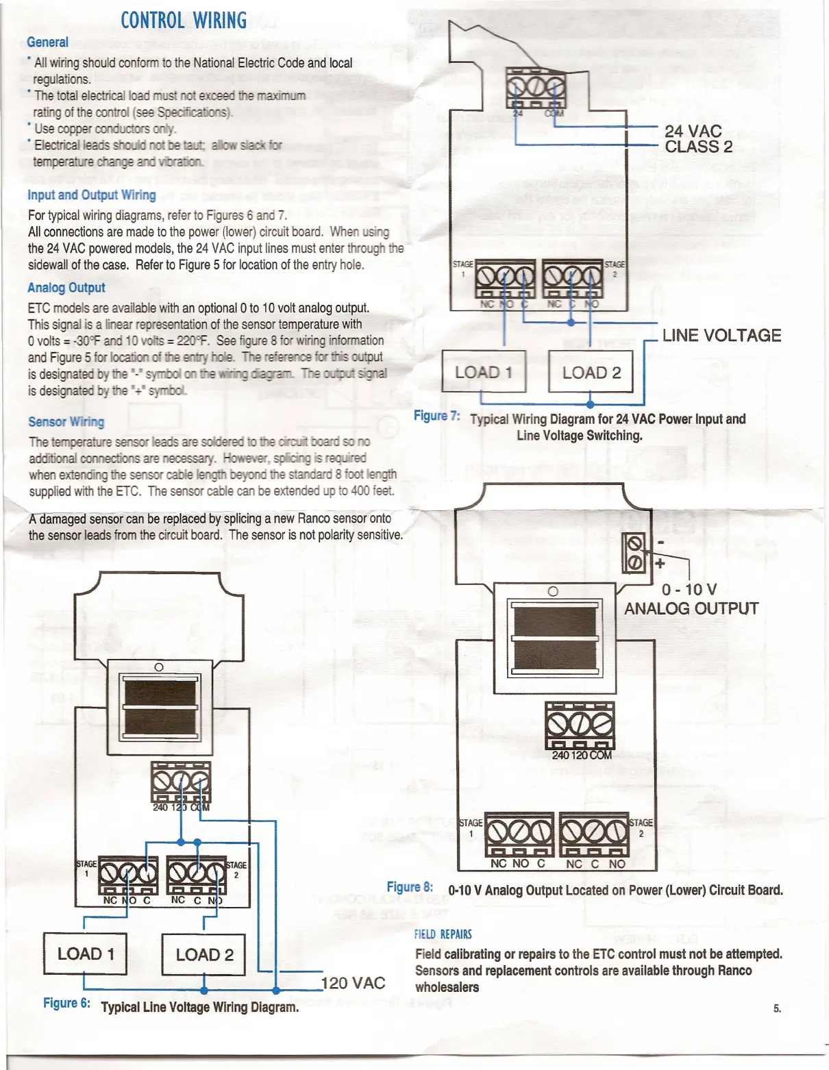
Input and Output Wiring
For typical wiring diagrams, refer to Figures 6 an 7.
All connections are made to the power (lower) circuit board. When
the
24
VAC powered models, the
24
VAC input lines must enter throug e
sidewall of the case. Refer to Figure
5
for location of the entry hole.
Analog Output
ETC models are available with an optional
0
to
10
volt analog output.
This signal is a
Ii
ear
representation of the sensor temperature with
o
volts
=
-30'f
an
=
22 .
See figu e
8'
wiri g i formation
and Figure 5 I r ut
is desig a
is designa
e t6lTlj:>eral:lITl
addffionalcoru'lediOOs
when exte e se e I e ~
supplied with the ETC. The sensor cable can be extended up to 400 lee .
- amaged sensorcan be replaced-by splicing a new Rancosensor onto
the sensor leads from the cirCUITboard. The sensor is not polarity sensitive.
==
----L.
~tX~~
2
I
LINE VOLTAGE
~~I
Figure 7: Typical Wiring Diagram for 24 VAC Power Input and
Line Voltage Switching.
+
o
0 -10 V
ANALOG OUTPUT
'~~~;"
NC NO C NC C NO
Figure 8:
0.10
V Analog Output Located on Power (Lower) Circuit Board.
fiELD REPAIRS
Field calibrating or repairs to the ETC control must not be attempted.
Sensors and replacement controls are available through Ranco
wholesalers