EasyManua.ls Logo

Ranger R26EX - User Manual

Ranger R26EX
30 pages
Print Icon
To Next Page IconTo Next Page
Loading...
MODEL
R26EX
TIRE CHANGER
FOR SERVICING
AUTOMOBILE
AND LIGHT TRUCK
SINGLE PIECE
TIRES / WHEELS
REVISED 12/11/06
INSTALLATION AND OPERATION MANUAL
SHIPPING DAMAGE CLAIMS
When this equipment is shipped, title passes to the
purchaser upon receipt from the carrier.
Consequently, claims for the material damaged in
shipment must be made by the purchaser against the
transportation company at the time shipment is
received.
BE SAFE
Your new Ranger tire changer was designed
and built with safety in mind. However, your
overall safety can be increased by proper train-
ing and thoughtful operation on the part of the
operator. DO NOT operate or repair this equip-
ment without reading this manual and the
important safety instructions shown inside.
1645 Lemonwood Dr.
Santa Paula, CA. 93060, USA
Tel: 1-805-933-9970
Fax: 1-805-933-9160
Keep this operation manual near the
machine at all times. Make sure that
ALL
USERS read this manual .
PLEASE READ THE ENTIRE CONTENTS OF THIS MANUAL PRIOR TO
INSTALLATION AND OPERATION. BY PROCEEDING YOU AGREE THAT YOU
FULLY UNDERSTAND AND COMPREHEND THE FULL CONTENTS OF THIS
MANUAL. FORWARD THIS MANUAL TO ALL OPERATORS. FAILURE TO
OPERATE THIS EQUIPMENT AS DIRECTED MAY CAUSE INJURY OR DEATH.
PANZITTA SALES & SERVICE
72 George Avenue
Wilkes-Barre, PA 18705
570-822-6720 800-822-6720
www.panzittasales.com
Question and Answer IconNeed help?

Do you have a question about the Ranger R26EX and is the answer not in the manual?

Summary

General Warning

Shipping Damage Claims

Safety Precautions

R26 EX Service Parts - Body

R26 EX Service Parts - Vertical Arm

R26 EX Service Parts - Control Pedals

R26 EX Service Parts - Turntable

R26 EX Service Parts - Bead Breaker Cylinder

R26 EX Service Parts - Gearbox

R26 EX Service Parts - Inflation Pedal

R26 EX Service Parts - Air Valve

R26 EX Service Parts - Air Tank

R26 EX Service Parts - Right Tower

R26 EX Service Parts - Assist Tower

Overview

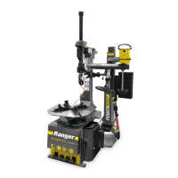
The device described in this manual is the Ranger R26EX Tire Changer, designed for servicing automobile and light truck single-piece tires and wheels. It is a robust and versatile piece of equipment intended for professional use in automotive service environments.

Function Description:

The Ranger R26EX Tire Changer is primarily used for mounting and dismounting tires from wheels. Its core function involves securely clamping the wheel, breaking the bead of the tire from the rim, and then rotating the tire to separate it from or mount it onto the wheel. The machine incorporates a "Power Assist" system, indicating advanced features for easier and more efficient tire changing, especially for challenging or low-profile tires. This power assist likely includes pneumatic or hydraulic components that aid in manipulating the tire and bead, reducing manual effort and potential for damage. The overall design suggests a focus on speed, safety, and precision in tire service operations.

Important Technical Specifications:

While specific numerical values for all components are not explicitly listed in a consolidated table, the exploded diagrams and parts lists provide insights into the machine's construction and capabilities:

  • Body and Frame: The main body (Ref. 101) is a substantial structure, supporting the turntable, vertical arm, and bead breaker. Screws and washers of various sizes (e.g., M8X20, M5X8, M6X10, M10X200, M10X160) indicate a strong, bolted assembly.
  • Turntable (Ref. 401A): This is a critical component, designed to securely hold the wheel during operation. It features clamps (Ref. 410) and slide plates (Ref. 415) for adjustable gripping. The turntable assembly includes various O-rings (e.g., Ø25X3.1, Ø30X18.5X5, Ø80X3.1, Ø80X5.7) and a piston (Ref. 451.5) within a cylinder assembly (Ref. 451), suggesting a pneumatic or hydraulic clamping mechanism for precise and powerful wheel retention. The presence of a "Turntable cap" (Ref. 405) and "Disk key" (Ref. 407) points to a well-engineered rotational system.
  • Vertical Arm (Ref. 227): This arm, also referred to as the "Horizontal arm" in some parts, is a key operational component. It houses the mounting head (Ref. 201) and is likely adjustable to accommodate different wheel diameters. The arm's movement is controlled by a "Hand-control valve" (Ref. 219) and a "Cylinder body" (Ref. 228) with associated O-rings (Ø10X2) and Y-rings (65X8), indicating pneumatic control for precise positioning. The "Locking cylinder assembly" (Ref. 269) further ensures stability during operation.
  • Bead Breaker Cylinder (Ref. 5-A): This assembly is responsible for breaking the tire bead from the rim. It comprises a "Shaft for cylinder" (Ref. 514), a piston (Ref. 527), and a "Cylinder body" (Ref. 529) with O-rings (Ø185X5.7) and a Y-ring (Ø30X20X7). The "Positioning spacer" (Ref. 511) and various unions (G1/8"-Ø8, G1/4"-Ø8) suggest pneumatic operation for powerful bead breaking. The shaft length is specified as 597mm.
  • Control Pedals (Ref. 3-A): The machine is operated via multiple foot pedals (Ref. 301, 301A, 302), which control various functions such as turntable rotation, bead breaking, and possibly inflation. These pedals are linked to "Valve assembly" (Ref. 334, 340) components, including "Valve body" (Ref. 334.2, 340.2), "Valve pin" (Ref. 334.7, 340.3), springs, and unions (G1/8"-Ø8, G1/8"-Ø6), indicating pneumatic control. A "Reverse lever" (Ref. 324A) is also present, likely for directional control of the turntable.
  • Gearbox (Ref. 6-A): This unit, including a "Lower gearbox housing" (Ref. 601) and "Upper gearbox housing" (Ref. 610), is responsible for driving the turntable. It contains a "Gear wheel with support" (Ref. 609), "Spindle" (Ref. 606, 355mm length), "Worm screw" (Ref. 617), and various bearings (6208, 6010, 30205) and disk keys (14X55, 6X20). The presence of a "Belt pulley" (Ref. 621) and "Motor pulley" (Ref. 625) indicates a belt-driven system.
  • Motor (Ref. 631): The motor is listed as "DISCONTINUED" but its specifications are 110/200V-50/60HZ, indicating a versatile power input. A "Capacitor" (Ref. 632) is also part of the electrical system.
  • Air Valve (Ref. 8-A): This assembly manages the pneumatic functions of the machine. It includes a "Valve support" (Ref. 803), "Seeger ring" (Ref. 805), "Sealing ring" (Ref. 806), "Pressing washer" (Ref. 807), and various unions (G1/4"-Ø8, G3/8"-Ø12).
  • Air Tank (Ref. 914): This component stores compressed air for the pneumatic operations. It includes a "Safe valve" (Ref. 913, 0.1-1.5Mpa), "Single direction valve" (Ref. 907, 0.1-1.5Mpa), and a "Valve body" (Ref. 928, 1"). Various PU hoses (Ø8X5, Ø12) and unions (3-G1/4", 2-G1/4", G1") connect the air tank to other pneumatic components.
  • Right Tower (Ref. R001): This structural component supports the bead breaker and other mechanisms. It includes a "Bead break disk" (Ref. R021), "Moving spindle" (Ref. R014), "Bend arm" (Ref. R017), and a "Cylinder assy" (Ref. R042, Ø100XØ20X365) with O-rings (25X3.1, 100X5.7, 14.5X2, 100X3.1).
  • Assist Tower (Ref. L001): This optional or integrated tower provides additional assistance for tire changing, especially for larger or stiffer tires. It features a "Cylinder spindle" (Ref. L021A), "Moving bracket" (Ref. L036), and a "Cylinder shaft" (Ref. L087) with associated O-rings (25X3.1, 100X5.7, 14.5X2). It also includes a "Pressure-reducing valve" (Ref. L027, Max. 10bar) and various PU hoses (14X1, 6X4) and unions (G1/8"-Ø6).

Usage Features:

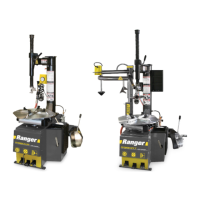
The Ranger R26EX is designed for ease of use and operator safety.

  • Power Assist System: The "Power Assist" feature (indicated by the graphic on page 1) significantly reduces the physical effort required to change tires, making it suitable for high-volume shops and for handling difficult tire/wheel combinations. This likely involves pneumatic cylinders that help with bead breaking, lifting, and positioning the tire.
  • Foot Pedal Controls: The use of multiple foot pedals (page 9) allows for hands-free control of various operations, improving efficiency and safety by keeping the operator's hands free to manipulate the tire and wheel.
  • Adjustable Components: The turntable clamps and vertical arm are designed to be adjustable, accommodating a wide range of automobile and light truck wheel sizes.
  • Safety Warnings: The manual prominently displays "WARNING" and "READ FIRST" labels, emphasizing the importance of reading the manual before operation to prevent injury or death. This indicates a focus on operator safety during use.
  • Ergonomic Design: While not explicitly stated, the layout of controls and the power assist system suggest an ergonomic design aimed at reducing operator fatigue.

Maintenance Features:

The manual provides detailed exploded diagrams and parts lists, which are crucial for maintenance and repair.

  • Comprehensive Parts Lists: Each major assembly (Body, Vertical Arm, Control Pedals, Turntable, Bead Breaker Cylinder, Gearbox, Air Valve, Air Tank, Right Tower, Assist Tower) has a dedicated parts list with reference numbers, descriptions, specifications, and quantities. This allows for easy identification and ordering of replacement parts.
  • Discontinued Parts: The manual clearly marks "DISCONTINUED" parts (e.g., Bead breaker shoe Ref. 130A, Cylinder rear housing Ref. 430, Motor Ref. 631, Motor assembly Ref. 6-B, Inflation Pedal Assembly) which is important for users to know when sourcing replacements or considering upgrades.
  • Regular Inspection: Although not explicitly detailed in the provided pages, the presence of numerous washers, O-rings, and Seeger rings implies that regular inspection and replacement of these wear items would be part of routine maintenance to ensure proper sealing and function of pneumatic and mechanical systems.
  • Grease Containers: The "Grease container holder" (Ref. 119) and "Grease container" (Ref. 120, 152) indicate that lubrication is a critical aspect of the machine's maintenance, ensuring smooth operation of moving parts.
  • Hose and Union Replacements: The extensive use of PU hoses (e.g., Ø8X5, Ø6X1, Ø6X4, Ø12) and various unions (G1/4"-Ø8, G1/8"-Ø6, G1/8"-Ø8, G3/8"-Ø12) suggests that pneumatic system integrity is vital, and these components may require periodic inspection and replacement due to wear or leaks.
  • Accessibility for Repair: The modular breakdown of the machine into distinct assemblies (e.g., gearbox, cylinders, control pedals) suggests that individual components can be accessed and repaired without necessarily disassembling the entire machine, simplifying maintenance procedures.

Ranger R26EX Specifications

General IconGeneral
BrandRanger
ModelR26EX
CategoryTyre Changers
LanguageEnglish

Related product manuals