EasyManua.ls Logo

Ranger RCI-2950 Service Manual

Ranger RCI-2950
154 pages
To Next Page IconTo Next Page
Page #1 background imageLoading...
Page #1 background image
RCI 2950 Service Manual
Table of Contents
Specifications
Controls and Connections
Basic Programming Procedures
Technical Analysis of the circuits
Transistors Voltage Chart
RCI SECRETS
REPAIR TRICKS
DIAGRAMS
Main PCB Schematic Diagram
CPU PCB Schematic Diagram
Chassis Exploded View Drawing
Inter-connection Diagram
PCB Layouts and Parts
(EPT295013Z)
Main PCB Parts Layout Top View
Main PCB Copper Side View
LCD PCB (EPT295021Z)
CPU PCB (EPT295043Z)
MIC UP/DW (EPT295080Z)
MIC Jack PCB (EPT295070Z)
SWR PCB (EPT360040Z)
VR (A) PCB RF/MIC VOL/SQ (EPT295050Z)
VR (B) PCB RF/CAL (EPT295060Z)
CH / Switch PCB (EPT295090A)
MODE PCB (EPT295090Z)
Push Button Switch PCB (EPT295031Z)
PARTS LISTS
Capacitors
Coils, Transformers, Crystals, Filters
Resistors
IC's, Transistors
Diodes
Wire, Jumpers, Connectors
Chassis, Miscellaneous & Mechanical Parts
RADIO MODIFICATIONS
MODIFY FOR 26 Mhz -32 Mhz
MODIFY FOR 25 Mhz -33 Mhz
Ham to CB Mode Modification
INCREASE YOUR POWER ! !
HEAVY SWINGER Mod (Modulation)
TUNE UP/MOD
Upgrading AM detection
INCREASE AUDIO
Add an Automatic SQUELCH
BATTERY PROBLEMS
CLARIFIER MOD
CAR'S LIGHTER Install
LCD & LEDS
MIKE Wiring
Protect From Polarity Inversions
MOD FOR FASTER SCAN SPEED
EXTERNAL S-METER
TALK BACK MODIFICATION
TONE MODIFICATION
ALIGNMENT PROCEDURES
TX Alignment
TX Alignment Locations
RX Alignment
RX Alignment Locations
PLL Alignment
PLL Alignment Locations
Este manual es una recopilación de las mejores páginas web. Radioaficion.com,.. No ofrece ninguna garantia sobre el contenido del mismo, ni se hace responsable de la
manipulación indebida de los equipos

Table of Contents

Question and Answer IconNeed help?

Do you have a question about the Ranger RCI-2950 and is the answer not in the manual?

Ranger RCI-2950 Specifications

General IconGeneral
DisplayLCD
MicrophoneDynamic
Weight5 lbs
Microphone Impedance600 ohms
Input Voltage13.8 VDC
Antenna Impedance50 ohms
Frequency Range28.000 - 29.700 MHz
ModesAM, FM, USB, LSB, CW
Power Supply13.8V DC

Summary

RCI-2950 Specifications

Key Features Overview

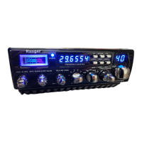
Summary of the radio's main operational features and capabilities.

General, Transmitter, and Receiver Specs

Detailed technical specifications for the unit's general, transmit, and receive functions.

Controls and Connections

Introduction to Operating Procedures

Explains basic operating procedures for the amateur mobile transceiver.

Front Panel Controls and Ports

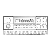
Detailed description of each control, button, display, and connection port.

Basic Programming Procedures

Frequency Selection Methods

Describes three distinct methods for selecting operating frequencies.

Frequency and Memory Scanning

Procedures for scanning frequencies and programmed memory channels.

Offset Frequency Operation

How to program and use the split frequency feature for repeater use.

Technical Analysis of Circuitry

Frequency Synthesizer and Transmit Circuit Analysis

Analysis of the frequency synthesizer, transmit mixer, filters, and amplifier stages.

Receiver Circuit Analysis

Details on the superheterodyne receiver stages, including IF conversions and filters.

Transistor Voltage Chart

Transistor Voltage Readings by Mode

Table showing voltage readings for transistors in various modes (RX/TX).

Repair Tricks and Common Faults

Front End Protection and Frequency Selection Troubleshooting

Troubleshooting common issues like diode failures and frequency selection problems.

Common Operational Faults and Solutions

Identifies frequent problems such as battery drain and regulator issues.

Schematic Diagrams

Main PCB Schematic

Complete schematic diagram of the main printed circuit board.

CPU PCB Schematic

Schematic diagram for the central processing unit printed circuit board.

Chassis Exploded View and Inter-connection Diagram

Visual layout of chassis parts and how major boards connect.

PCB Layouts

LCD PCB (EPT2950217) Layout

Trace layout for the LCD display PCB.

CPU PCB (EPT295043Z) Layout

Trace layout for the CPU PCB.

Microphone Related PCBs Layouts

Layouts for the MIC UP/DW and MIC Jack PCBs.

Other PCBs Layouts

Layouts for VSWR, VR, CH/SW, MODE, and Push Button PCBs.

Parts Lists

Main PCB Capacitors

Detailed list of capacitors for the main PCB.

Main PCB Coils, Transformers, Crystals, Filters

List of inductive and filtering components for the main PCB.

Main PCB Resistors

List of variable and fixed resistors for the main PCB.

Main PCB Integrated Circuits, Transistors, Diodes

List of integrated circuits, transistors, and diodes for the main PCB.

Main PCB Wire, Jumpers, Connectors, Chassis Parts

List of wiring, connectors, chassis, and miscellaneous parts.

Radio Modifications

Frequency Range Expansion Mod

Modifying the radio for operation between 26 MHz and 32 MHz.

Mode and Channel Modifications

Enabling HAM/CB modes and adding a Channel 9 emergency key.

Power and Audio Enhancements

Modifications to increase output power and improve audio quality.

Performance Tuning and Squelch Mods

Adjustments for performance, AM detection, and adding automatic squelch.

Battery Management and Clarifier Mod

Solutions for battery issues and unlocking the clarifier function.

Feature Enhancements (LCD, Mic, Scan, Talkback)

Mods for LCD backlight, microphone wiring, scan speed, and talk-back.

Protection and Miscellaneous Modifications

Mods for polarity protection, external S-meter, and tone capability.

Alignment Procedures

Transmitter (TX) Alignment

Step-by-step guide for aligning transmitter functions.

TX Alignment Locations

Visual reference showing adjustment points on the PCB for TX alignment.

Receiver (RX) Alignment

Step-by-step guide for aligning receiver functions.

RX Alignment Locations

Visual reference showing adjustment points on the PCB for RX alignment.

PLL Alignment

Step-by-step guide for aligning the Phase-Locked Loop circuit.

PLL Alignment Locations

Visual reference showing adjustment points on the PCB for PLL alignment.

Related product manuals