EasyManua.ls Logo

Ranger RCI-2950DX - User Manual

Ranger RCI-2950DX
3 pages
Print Icon
To Next Page IconTo Next Page
Loading...
Equipment required for Alignment procedure:
• DC Power Supply ( 13.8 Vdc, 20A )
• Oscilloscope (50 MHz), with X10 probe
• 50 dummy load
• Frequency Counter - 100 MHz
• Digital voltmeter or Multimeter
• RF Signal Generator
• Audio Generator
• Automatic Distortion Meter
• SINAD Meter
• RF Wattmetter ( 25~60 MHz, 100W )
• Automatic Modulation Meter
To view Main PCB Adjustment for location of adjustment points, please see this
drawing After viewing, press "back" to return to this page.
The following steps are required to re-align the RCI-2950DX:
Caution:
Alignment should only be attempted by personnel trained in RF
product testing and alignment.
PLL Synthesizer / Oscillator Frequency Alignment:
1. PLL2 - VCO Voltage:
A. Set radio to 24.890 MHz, AM RX mode, connect multimeter to TP10.
Adjust L14 for 1.0 Vdc ± 0.1.
B. Set frequency to 29.699 MHz, AM RX mode, connect multimeter to TP10.
Adjust L14 for 4.5 Vdc ± 0.1.
2. PLL1 - VCO Voltage:
A. Set radio to 24.890 MHz, AM RX mode, connect multimeter to TP10.
Adjust L13 for 1.0 Vdc ± 0.1.
B. Set frequency to 32.000 MHz, AM RX mode, connect multimeter to TP10.
Adjust L13 for 6.5 Vdc ± 0.1.
2. AM Frequency:
Set radio to AM RX mode, clarifier to 12 o'clock,. Connect frequency counter to
TP16.
Adjust VC2 to 10.1 MHz ± 10Hz.
3. VCO Output:
Set radio to 28.000 MHz, AM RX mode, connect oscilloscope to TP3.
Adjust L17 to 38.6950 MHz (maximum output).
4. AM OSC:
Set radio to AM TX mode, modulation off, connect frequency counter to TP5.
Adjust L18 to obtain 10.6950 MHz ± 10Hz.
5. USB OSC:
Set radio to USB TX mode, modulation off, short TP6 to ground, connect
frequency counter the TP5.
Adjust L20 to 10.6975 MHz ± 10Hz.
6. LSB OSC:
Set radio to LSB TX mode, modulation off, connect frequency counter to TP5.
Adjust L19 to 10.6925 MHz ± 10Hz.
This completes this stage of the alignment procedure.
Question and Answer IconNeed help?

Do you have a question about the Ranger RCI-2950DX and is the answer not in the manual?

Summary

PLL Synthesizer and Oscillator Frequency Alignment

PLL2 VCO Voltage Adjustment

Adjusts VCO voltage for PLL2 at specific frequencies (24.890 MHz and 29.699 MHz) using L14.

PLL1 VCO Voltage Adjustment

Adjusts VCO voltage for PLL1 at specific frequencies (24.890 MHz and 32.000 MHz) using L13.

AM Frequency Alignment

Sets AM frequency and adjusts the clarifier to 12 o'clock using VC2.

VCO Output Alignment

Sets VCO output to 38.6950 MHz using L17.

Receiver Alignment Procedures

Transmitter Alignment Procedures

SSB and AM RF Power Adjustment

Adjusts SSB and AM RF power output using L-coils and VR12/VR15.

TX AM Modulation Adjustment

Adjusts AM modulation to 100% using VR17.

Overview

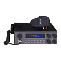
This document outlines the alignment procedures for a radio, likely a transceiver, given the presence of both receiver and transmitter alignment sections. The device appears to be a multi-mode radio, supporting AM, FM, USB, and LSB modes, and operates within the 24.890 MHz to 32.000 MHz frequency range for various functions, with specific operational frequencies like 28.295 MHz and 28.495 MHz for alignment.

Function Description

The device is a radio, capable of both receiving and transmitting signals across multiple modulation types. Its primary function is two-way radio communication. The alignment procedures detail how to calibrate its various internal components to ensure optimal performance in both reception and transmission. Key functions include:

  • PLL Synthesizer/Oscillator Frequency Alignment: This ensures the internal frequency generation is accurate for all operating modes. It involves adjusting VCO (Voltage Controlled Oscillator) voltages for PLL1 and PLL2, and calibrating the AM, USB, and LSB oscillators.
  • Receiver Alignment: This section focuses on optimizing the radio's ability to receive signals. It covers sensitivity adjustments for AM, USB, and LSB, distortion minimization for FM, noise blanker (NB) adjustment, and calibration of the S-meter for both AM and USB modes. Squelch adjustments for AM and SSB are also included to manage background noise during reception.
  • Transmitter Alignment: This part deals with calibrating the radio's transmission capabilities. It includes setting driver bias for the power amplifier, adjusting SSB and AM RF power output, calibrating the power meter, and setting AM modulation depth. A CW side-tone signal adjustment is also present, indicating CW (Continuous Wave) transmission capability.

Important Technical Specifications

Based on the alignment procedures, several technical specifications and operational parameters can be inferred:

  • Frequency Range: The radio operates within a frequency range that includes 24.890 MHz, 28.000 MHz, 28.295 MHz, 28.305 MHz, 28.495 MHz, 29.699 MHz, and 32.000 MHz for various alignment steps. The RF Wattmeter specification (25-60 MHz) further supports this range.
  • Modulation Types: Supports AM (Amplitude Modulation), FM (Frequency Modulation), USB (Upper Sideband), LSB (Lower Sideband), and CW (Continuous Wave).
  • Power Output:
    • SSB Peak RF Power Output: 21 watts.
    • AM RF Power Output: 10 watts.
  • Receiver Sensitivity (AM): Better than 0.5 µV for 10 dB SINAD.
  • Audio Modulation: Standard 1 KHz audio tone for modulation, with 30% modulation level for AM and ±3 KHz deviation for FM.
  • Internal Oscillator Frequencies:
    • AM OSC: 10.6950 MHz ± 10Hz.
    • USB OSC: 10.6975 MHz ± 10Hz.
    • LSB OSC: 10.6925 MHz ± 10Hz.
  • VCO Voltage Ranges:
    • PLL2: 1.0 Vdc to 4.5 Vdc.
    • PLL1: 1.0 Vdc to 6.5 Vdc.
  • Intermediate Frequencies (IF): The presence of a 10.1 MHz adjustment (VC2) suggests an IF stage at this frequency.
  • Power Requirements: Requires a DC Power Supply of 13.8 Vdc, 20A.
  • Test Equipment Required:
    • DC Power Supply (13.8 Vdc, 20A)
    • Oscilloscope (50 MHz), with X10 probe
    • 50 Ω dummy load
    • Frequency Counter - 100 MHz
    • Digital voltmeter or Multimeter
    • RF Signal Generator
    • Audio Generator
    • Automatic Distortion Meter
    • SINAD Meter
    • RF Wattmeter (25~60 MHz, 100W)
    • Automatic Modulation Meter

Usage Features

The document primarily focuses on internal alignment rather than user operation. However, some usage features can be inferred:

  • Mode Selector: The radio has a mode selector for AM, FM, USB, and LSB.
  • RF Gain Control: A fully clockwise position indicates maximum gain.
  • Squelch Control: Adjustable to minimize background noise.
  • Volume Control: Standard audio output adjustment.
  • Clarifier: A control for fine-tuning received frequencies, set to "12 o'clock" for alignment.
  • NB-ANL Switch: A Noise Blanker/Automatic Noise Limiter switch to reduce impulse noise.
  • SWR/S/RF Switch: A switch to select between SWR (Standing Wave Ratio), S-meter (Signal Strength), and RF power display.
  • Mic Gain Control: Adjustable for optimal microphone input.
  • SSB Power Control (VR12): Allows adjustment of SSB output power.
  • CW Jack: A dedicated jack for CW operation, likely for connecting a key.
  • External Speaker Jack: For connecting an external audio output device.

Maintenance Features

The document is essentially a maintenance manual for alignment. Key maintenance features include:

  • Detailed Alignment Procedures: Step-by-step instructions for calibrating various internal circuits, including PLL, receiver, and transmitter sections.
  • Test Points (TPs): Specific test points (TP1, TP3, TP5, TP6, TP7, TP8, TP9, TP10, TP16) are designated for connecting test equipment, facilitating diagnostic and adjustment processes.
  • Adjustable Components (Ls, VRs, VC): Numerous inductors (L), variable resistors (VR), and variable capacitors (VC) are identified as adjustment points, allowing technicians to fine-tune the radio's performance. Examples include L3, L4, L5, L6, L7, L8, L10, L11, L12, L13, L14, L17, L18, L19, L20, L33, L40, L42, L43, L44, VR1, VR2, VR3, VR4, VR9, VR10, VR11, VR12, VR13, VR15, VR17, and VC2.
  • "Shorting PCB": The instruction to remove and reconnect a "Shorting PCB" from TP7, TP8, and TP9 indicates a specific internal configuration or test setup required for certain adjustments, highlighting a modular or accessible design for maintenance.
  • Safety Precaution: The "Caution" note emphasizes that alignment should only be attempted by "personnel trained in RF product testing and alignment," indicating the complexity and potential for damage if performed incorrectly.
  • Visual Aid Reference: The instruction "To view Main PCB Adjustment for location of adjustment points, please see this drawing" suggests the availability of a PCB layout diagram, which is crucial for locating the numerous adjustment points.

In summary, this document describes a sophisticated multi-mode radio with extensive internal adjustments for optimal performance across various communication modes. Its design facilitates detailed calibration and maintenance by trained personnel, ensuring precise frequency control, sensitive reception, and accurate power transmission.

Ranger RCI-2950DX Specifications

General IconGeneral
BrandRanger
ModelRCI-2950DX
CategoryRadio
LanguageEnglish

Related product manuals