ATTENTION!
ATTENTION!
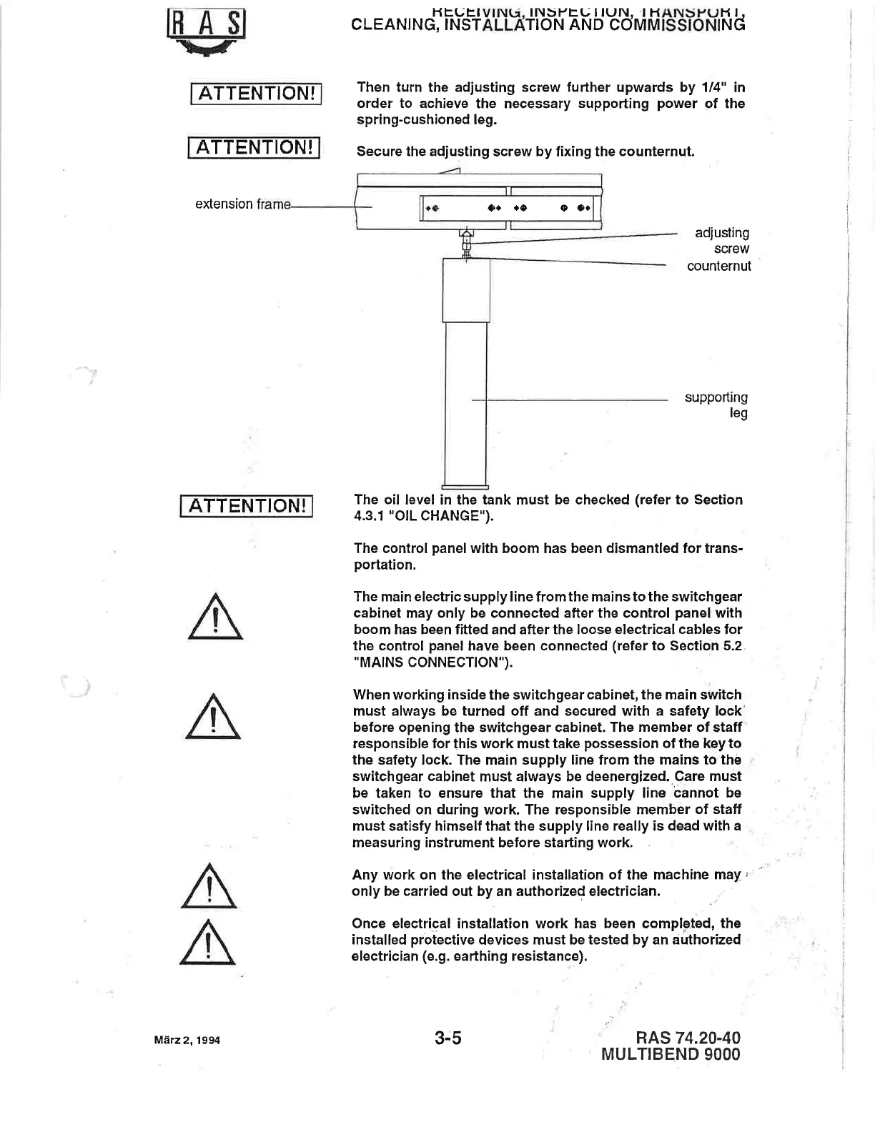
eXension
ATTENTION!
l-tEUElVlNl.r. lNbl-trU I
lUN. I HANUI"UI'I l.
CLEANING,
INSTALLATION
AND
COMMISSIONING
Then turn
the
adjusting screw fufther
upwards
by
1/4" in
order to
achieve the necessary
supporting
power
of the
spring-cushioned
leg.
Secure the adjusting
screw by
fixing the counternut.
adjusting
screw
counternut
suppofting
leg
The oil
level in the tank must be checked
(refer
to
Section
4.3.1 "OlL CHANGE").
The control
panel
with boom has been dismantled for trans-
portation.
The
main
electric supply
line from
the mains to the switchgear
cabinet may only be connected after the control
panel
with
boom
has been fitted and after the loose electrical cables for
the control
panel
have been
connected
(refer
to
Section 5.2
"MAINS
CONNECTION").
When working
inside
the switchgear
cabinet, the main switch
must always be
turned off and
secured with a safety lock
before
opening the switchgear cabinet.
The member of
staff
responsible for this work
must
take
possession
of the key to
the
safety lock The main supply line from
the
mains to
the
switchgear
cabinet
must always be deenergized.
Care must
be taken to ensure that the main supply line
cannot be
switched on during
work. The responsible
member
of
staff
must satisfy
himself
that
the
supply line really is dead with
a
measuring instrument before starting work.
Any work on the etectrical installation of the machine
may
,
only
be carried out by an authorized electrician.
I
Once etectrical instaltation work has been completed, the
installed
proiective
devices must be tested
by an airthorized
electrician
(e.9.
eafthing resistance).
RAS
74.20-40
MULTIBEND
9OOO
o+.o oo.
Marz
2, 1994
3-5
I
i
l
l.
I
 Loading...