EasyManua.ls Logo

Rath 2500-LUPSM - User Manual

Rath 2500-LUPSM
2 pages
To Next Page IconTo Next Page
Loading...
N56W24720 N. Corporate Circle • Sussex, WI 53089
800-451-1460 • www.rathcommunications.com
Made in the USA
3 Year Warranty
RP8500LUPSM
Ver. 1
08/20
Installation Guide
Relay Control Card 2500-LUPSM
Relay Control Card
Part #: 2500-LUPSM
1. The Relay Control Card is pre-installed in the UPS and the DB9 connector is pre-wired to the diagram below.
2. Using the diagram as a guide, wire in the connections to your monitoring device.
3. Plug the DB9 connector into the Relay Control Card.
4. Plug the supplied power adapter into an open outlet on the UPS.
Pin Assignment
Pin1
Pin2
Pin5
Pin7
Pin9
Function
UPS Fault
Summary Alarm
Common (For Relays)
Battery Low
Utility Line Fail
I/O
O/P
O/P
O/P
O/P
O/P
PIN 5
PIN 1
PIN 7
PIN 2
PIN 9
Question and Answer IconNeed help?

Do you have a question about the Rath 2500-LUPSM and is the answer not in the manual?

Rath 2500-LUPSM Specifications

General IconGeneral
BrandRath
Model2500-LUPSM
CategoryController
LanguageEnglish

Summary

Installation Guide Relay Control Card 2500-LUPSM

Installation Procedure

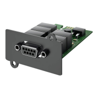
Steps for installing and connecting the Relay Control Card, including wiring and power adapter connection.

Pin Assignments and Functions

Details the pin assignments (1, 2, 5, 7, 9) and their corresponding functions and I/O types.

Appendix A: Relay Control Card RELAYIO500

Function Description by Status

Describes the conditions triggering specific status outputs for pin combinations (e.g., Pin1 Short to Pin5 indicates UPS Fault).