Do you have a question about the Rayburn 200SFW and is the answer not in the manual?
Warranty alterations may invalidate approval, affect warranty, and impact statutory rights.
Compliance with National and European standards is required for installation.
User/installer responsibility to wear protective clothing when handling materials.
Use only approved spare parts; avoid reconditioned or un-authorised copies.
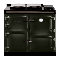
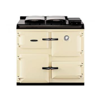
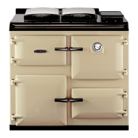
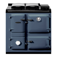
200SFW for cooking only; 212SFW for cooking and domestic hot water.
Heat output for 200SFW & 212SFW models with Ancit and wood logs.
Fuel distribution to hot water and appliance for Ancit and wood.
Weight specifications and confirmation of no electrical power supply requirement.
Specified flue gas mass flow and mean flue gas temperature.
Appliance meets BS EN 12815 and HETAS approval standards; tested fuels noted.
Combustion air and burn rate controlled by spinwheel and flue damper.
212SFW provides approx. 100 gallons hot water for household needs.
Doors must be locked closed during normal use, except for lighting/refuelling.
Warning about hot surfaces; use tool and heatproof glove for hotplate.
Doors must be locked closed during normal use, except for lighting/refuelling.
Petroleum coke must not be used as fuel.
Do not use aerosol sprays near the stove when it is alight.
Minimum 150mm clearance required from combustible materials.
Table detailing clearances to combustible and non-combustible walls/materials.
Electrical work must be done by a qualified electrician per BS 7671.
Details for the hot water system including cylinder, pipes, and pressure.
Recommends a 140 litre indirect hot water cylinder, lagged and fixed vertically.
Maximum water pressure is 1.75 bar; boiler capacity is 7 litres.
Primary flow/return pipes need 28mm min. diameter, max 10m length, lagged if >5m.
Flow pipe must have open vent; draw-off pipes must be dead-leg connections.
Towel rail heating is permitted under specific conditions for pipe length and lagging.
Boiler outputs are achieved by idling overnight and daytime cooking.
All systems require a drain tap at the lowest point.
Crucial notes regarding appliance operation and potential issues like overheating.
Overheating can cause knocking noise and boiling; actions to mitigate heat.
Procedures for connecting the boiler, including access and sealing.
Instructions for accessing and connecting the boiler for the 212SFW model.
Seal boiler face to locating face with fire cement and renew brickwork joints.
Requirements for preparing the installation site, including hearth and walls.
Hearth and adjacent walls must be solid, level, and conform to Building Regulations.
Cooker and flue installation must follow BS8303 and BS EN 15287-1:2007.
Boiler installation must comply with local Water Undertaking byelaws.
Guidelines for placing the cooker, including recess and wall clearances.
Cooker must be freestanding in a recess, not built-in solid at sides.
Tiles should not overlap the cooker top plate when installed near a wall.
Keep combustible materials away from cooker; work surface may fit to top plate.
Important notes regarding initial use, such as smoke and smell emission.
Initial use may produce smoke/smell due to protective oil; ventilate and lift lids.
Details on necessary air vents and ventilation provisions for the appliance.
Requires permanent unobstructed air vent of minimum 11cm² communicating to outside air.
Vent size must increase to 23.5cm² if a flue draught stabiliser is fitted.
Air inlet grilles must be positioned to avoid blockage.
Avoid extractor fans in the same room; compensating inlets are needed.
Specifications for the chimney, including draught, temperature, and flue type.
Minimum chimney draught requirement and mean flue gas temperatures for models.
Appliance cannot be installed in a shared flue system.
Procedures for checking the condition and suitability of existing chimneys.
Check chimney for leakage, porosity, and minimum flue dimension of 150mm.
Advice on chimney testing methods is available from HETAS Ltd.
Consult building control officer for chimney repairs/re-use regarding height and termination.
Chimney must be swept before the appliance is installed.
Guidelines for constructing a new chimney, including liner types.
New chimneys should use pre-cast liners (150mm min. diameter) per Building Regulations.
Chimney liners must be free of projecting internal jointing composition.
Recommendations for using factory-made insulated chimney systems.
Recommend ceramic lined chimneys complying with BS. 4543: Part 2.
Different flue connection configurations and installation considerations.
Cooker in recess requires 150mm clearance from flue pipe to brickwork.
Fill cavities above register plate; extend flue pipe into chimney throat.
Flue liner or insulated chimney size should be 150mm minimum.
Direct connection to brick flue is shown; horizontal runs are not permitted.
Connection to brick flue via flue pipe; square bends/horizontal runs prohibited.
All joints must be air-tight; air must only enter chimney via the cooker.
Unlined chimneys must be lined per current Building Regulations.
Provision for chimney sweeping must always be made.
Cement pipes/fittings prohibited within 2m of cooker; plain pipes not recommended.
Methods for connecting the cooker's flue outlet to the chimney system.
Cooker flue chamber adaptable for top or back flue outlets using a reversible socket.
Rear flue outlet requires brick flue; provision for condensate vessel and cleaning door.
Extended horizontal flue pipe connection allowed up to 150mm length.
No bend connections allowed in extended horizontal flue pipes.
Top flue outlet connects via 125mm pipe, sealed with rope/fire cement.
Flue pipe bends must not be less than 135° (45° from vertical) and include a cleaning door.
Addressing potential issues with tall chimneys and excessive updraughts.
Tall chimneys can cause excessive updraughts, affecting operation.
Recommend fitting an adjustable flue draught stabiliser above the flue pipe connection.
Step-by-step guide for installing the cooker and connecting components.
Position cooker, check hotplate joint integrity, and inspect underside.
For combustible material proximity, fit non-combustible insulation (min. 150mm either side) with a 16mm air gap.
Make good any opened joints with provided fire cement.
Replace hotplate ensuring even seating on soft rope, approx. 1.5mm proud of top plate.
Connect pipework to the boiler's flow and return tappings.
Instructions for fitting the flue chamber to the cooker.
Fit flue chamber with 1mm fire cement smear, ensuring a good seal to the cooker top.
Ensuring the bottomgrate is correctly positioned and operational.
Open doors, check bottomgrate position, and operate riddling lever.
Warning about potential permanent marking of the enamel surface.
Improper door closure can permanently mark the enamel surface.
Procedure for fitting the handrail brackets to the cooker top plate.
Replace travel nuts with handrail brackets, ensuring fibre washers are in position.
Mandatory installation of a carbon monoxide alarm in the dwelling.
Building regulations mandate a CO alarm in the same room as the appliance.
Steps for testing and commissioning the appliance after installation.
Heating contractor must demonstrate appliance operation and routine flue method to the user.
Verify the system is full of water and free from air pockets for the 212SFW.
Select and install the correct burning grate as per customer requirements.
Steps for lighting: open damper, add fuel, close doors, set spinwheel.
Allow the cooker to heat up gradually during initial lighting.
The boiler has a water capacity of 7 litres.
Information on firebrick lifespan, replacement, and maintenance.
Firebricks are high quality but expendable; require renewal over time.
Firebrick renewal is a manageable task for an average person.
Replacement bricks are available from Rayburn distributors.
Details on replacing firebricks, including quality and availability.
Firebricks are high quality but expendable; require renewal over time.
Replacement bricks are available from Rayburn distributors; quote manufacturing number.
Quote manufacturing number for inquiries regarding the Rayburn Cooker.
Information specific to the 212SFW model's hot water capabilities.
The 212SFW provides domestic hot water when kept alight overnight.
Satisfactory hot water supply depends on overnight operation and system conformity.
Overheating can cause knocking noise and boiling; actions to mitigate heat.
Drain boiler if freezing conditions are possible to prevent frost damage.
Do not light stove if heating system may be frozen; ensure system is free of ice and water circulates.
Guidelines for professional servicing and maintenance of the appliance.
Use qualified engineers for servicing and maintenance; use only authorised parts.
Do not make unauthorised modifications to the appliance.
Mandatory installation of a carbon monoxide alarm in the dwelling.
Building regulations mandate a CO alarm in the same room as the appliance.
Information on fume emissions, their causes, and immediate actions.
Properly installed/operated cooker will not emit fumes.
Occasional fumes from de-ashing/refuelling are normal; persistent emission must not be tolerated.
Immediate action for persistent fume emission: ventilate, let fire out, check flue blockage.
Open doors and windows to ventilate the room.
Let the fire go out or remove lit fuel from the cooker.
Check for flue or chimney blockage and clean if necessary.
Do not relight fire until fume cause is identified and remedied; seek professional advice if needed.
Procedures for storing the appliance during periods of non-use.
For prolonged non-use, clean thoroughly, remove ash, leave air controls open to reduce condensation.
List of available spare parts for the appliance.
List of available spare parts with part numbers and descriptions.
Replacement parts are available from local stockists.
Step-by-step guide for lighting the fire using wood and paper.
Ensure flue pipe is free of blockages.
Open doors, de-ash, lay wood/paper, add fuel, light.
Once fire is established, fill firebox with fuel up to the firedoor opening.
Step-by-step guide for lighting the fire using a gas poker.
Open doors, de-ash, insert gas poker.
Lay fuel, light poker, close doors, then add more fuel when alight.
Remove poker, replace ashpan, close doors, set spinwheel.
How to operate the appliance's control mechanisms.
Fire is controlled by the spinwheel on the ashpit door for air supply.
Flue chamber damper reduces chimney draught; markings help set best positions.
Specific settings for spinwheel and flue damper for optimal operation.
Specifies spinwheel open settings for coke (5 turns) and other fuels (3 turns).
Set flue damper fully open after refuelling and reset for best results; avoid fast temp increase.
Avoid excessive fire temperatures as they are unnecessary and can damage the cooker.
Clinker formation (melted ash) is the first symptom of overheating, damaging firebricks.
Replace damaged firebricks promptly; temporary repair with fire cement is possible.
Ensure the ashpit door is securely closed with the front plate catch.
Guidance on achieving efficient operation through overnight burning.
Appliance is designed for continuous burning; overnight burning yields best results.
Before bed, de-ash, empty, and refuel the firebox without overloading.
Ensure firebox and ashpit doors are closed securely; re-open spinwheel a quarter turn.
Turn dilution lever from left to right to open door at bottom, minimizing burning rate and condensation.
Dilution lever opening depends on chimney draught; requires 2-3 days to ascertain settings.
If fuel exhausts prematurely, reduce overnight draught by opening flue chamber damper further.
If fuel dies out, increase draught by partly closing flue chamber damper.
Best flue chamber damper position found by experiment; try low settings first.
In morning, open spinwheel (3 turns), damper (max), and riddle; then close damper when burning brightly.
Correct procedure for refuelling the appliance safely and efficiently.
Open flue damper fully before opening firebox door to prevent smoke spillage.
Reset the flue damper after refuelling; check flueway for blockages if smoke spills.
Fill firebox to the recommended level (bottom of door opening) and close door.
Deep fuel beds on low fire take time to heat oven/hotplate/boiler; allow time for coal/phurnacite ignition.
Close firebox door immediately after fuelling; open only for refuelling.
Steps for removing ash from the firebox and ashpan.
To de-ash, open chimney damper to maximum, then proceed.
Engage operating tool on the riddling lever knob.
Push tool back and forth 8-12 times to free the grate of ash.
Always de-ash before refuelling, at least three times daily.
If bottomgrate de-ashing fails, remove clinker/stones as described elsewhere.
Open ashpit door for access to ashpan; empty regularly.
Do not let ash touch the bottomgrate; it will burn out quickly.
Ensure ashpan is fully home for proper ashpit door closure.
Exception: Refuel before emptying ashpan/riddling when burning anthracite or phurnacite.
Procedure for removing clinker and the bottomgrate assembly.
Raise tool front, draw forwards to move grate support over lugs.
Lower front of removal tool to withdraw the complete grate assembly for cleaning.
Replace grate assembly in reverse order, ensuring positive location of support.
Clinker formation depends on burn rate; check weekly to prevent build-up.
Description of the two available bottomgrates and their fuel suitability.
Two bottomgrates available: one for coal/smokeless fuel (serrated edge), one for wood (round holes).
Handling the grate assembly requires two hands and gloves due to weight.
Stone, clinker, or shale may jam the grate; allow fire to cool before removal.
Allow fire to burn out and cool, then open ashpit door and remove ashpan.
Engage the grate assembly removal tool within the groove of the bottomgrate support.
Important warning regarding the use of the wood-only grate.
Wood grate must only be used for wood fuel to prevent damage.
Serrated edge grate can burn either fuel but may use more wood; ash bed is necessary for wood.
Parts get very hot; risk of serious injury. Operation should be done when appliance is not alight.
Fit wood grate by opening fire door, inserting with legs downwards and flat edges left/right.
Adjustment of secondary air calibration for converting to wood burning.
Converting to wood burning requires changing secondary air calibration from 6 to 8 aeration holes.
Guidelines for using the appliance's hotplate efficiently and safely.
Warning about hot surfaces; use tool and heatproof glove for hotplate.
Machined base utensils provide best hotplate results.
Circular plug in hotplate is for flue cleaning, not cooking.
Fuel firebox to a horizontal level for fast boiling or hotplate cooking.
Cooker top plate around hotplate gets hot; observe minimum clearances.
Instructions for using the main oven, including temperature control and calibration.
Do not exceed 250°C oven temperature to prevent appliance damage.
Thermodial indicates oven temp, but calibrate with an oven thermometer.
Spinwheel/damper adjustment for oven temp varies with chimney draught; experiment for local conditions.
The main oven may take up to 2 hours to reach operating temperature.
Maintain control by topping up firebox with 1-2 kg fuel and lightly de-ashing.
If closing damper causes smoke, open gradually until smoking stops.
Methods to reduce excessive top heat in the oven.
Place solid plain shelf on top runners to reduce top oven heat.
Guide to oven temperature settings for different cooking modes.
Check oven temperature using the pointer reading on the thermodial.
Non-boiler models may run hotter than specified due to site conditions.
Use of the warming oven for keeping food or plates warm.
Warming oven is for heating plates and keeping food warm, about 1/3-1/2 main oven temp.
Do not slam doors shut as this will wear away metal retaining catches.
Procedure for cleaning the appliance's flueways to maintain performance.
Clean flueway every four weeks for coke/anthracite/smokeless fuels; weekly for coal/wood.
Failure to keep flueways clean can cause dangerous gases and inferior performance.
Allow fire to burn out, open flue damper to max, remove flue chamber door, brush soot.
Remove hotplate plug, rake deposits into firebox.
Replace flue chamber door and hotplate plug, riddle bottomgrate for re-lighting.
If not in use, leave ashpit/flue chamber doors open to allow air passage and prevent condensation.
Guidelines for regular chimney sweeping and inspection.
Sweep annually and inspect/empty soot box every 3 months.
Use sweep brushes with wire centres and guide wheels.
Information on preventing, detecting, and acting during chimney fires.
Improper maintenance can lead to chimney fires caused by creosote ignition.
Prevent chimney fires with clean, intact, properly installed chimneys; professional sweep annually.
Chimney fire detection includes roaring noise, black smoke, sparks, and flames.
General cleaning instructions for the appliance's exterior and interior.
Clean vitreous enamelled surfaces daily with soapy cloth, then dry; wipe spills immediately.
Use cream cleanser for baked-on spills; soap pad for stubborn deposits on enamel.
Oven spills carbonise at high temp; brush off. Oven door removable for cleaning.
Raise insulating covers to cool before cleaning; use wire brush for cast iron hotplate.
Use AGA approved cleaners for vitreous enamel; not for chrome/stainless steel.
Clean insulating covers with non-abrasive detergent and polish with soft duster.
Tips and advice for using the oven and hotplate for various cooking tasks.
Oven is indirectly heated, allowing full use of the cooking space.
The main oven is hotter at the top than the bottom.
Low idling heat is suitable for slow cooking of dishes like casseroles and soups.
Cast iron oven floor is hotter than conventional cookers; no need to blind bake pastry.
Turn food during cooking for perfect baking results.
Grilling occurs at the top of a hot oven; use meat tray with grill rack for fat collection.
Thermodial gauge provides oven temperature indication; it will fluctuate when doors are opened.
Meat tray fits oven runners, leaving shelves free for other dishes.
Oven grid shelves are non-tilt; fit with upstand to top and back.
Solid plain shelf can be used as a baking sheet or heat deflector.
Do not use abrasive pads or oven cleaners on the appliance.
Avoid placing very wet clothes on the handrail to prevent enamel crazing.
Initial use may produce smoke/smell due to protective oil; ventilate and lift lids.