2 | nVent.com
Preparation for Mounting
Open the knockouts as required on the base unit. The holes are sized for the PG-9 threaded strain relief provided in the kit.
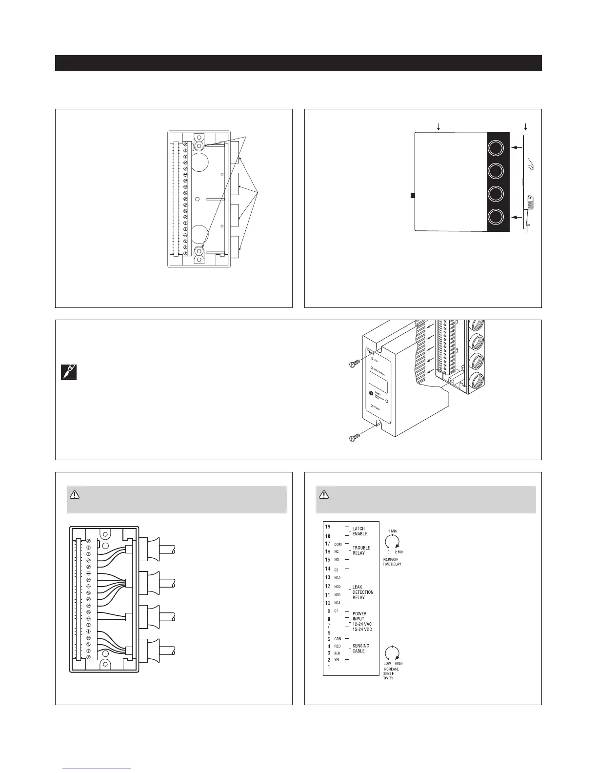
Figure 5: Terminal block wiring
Figure 6: Typical terminal block label
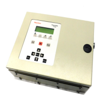
For Wall Mounting
Use the two holes in the
back plate to mount the
TTC-1 base unit to the
wall using suitable wall
fasteners. The mounting
holes are 4mm diameter,
separated by 85mm (center
to center). The mounting
screw holes are recessed
into a molded well that
is 7 mm in diameter. It is
recommended to use a J15
metric screw with a head
diameter small enough to
fit into the molded well.
For proper orientation, the
terminal strip must be on the left, as shown in Figure 2.
Figure 2: Wall mounting
Cable entry
knockouts
holes 85mm
(center to
center)
1 2 3 4 5 6 7 8 9 10 11 12 13 14 15
ID:
TRACETEK
19181716151413121110987654321
TROUBLE
RELAY
LEAK
DETECTION
RELAY
POWER
INPUT
SENSOR
LEADER
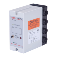
Loosen the two captive screws at least 10 full turns. You may
hear a click when screw is fully released. Use a gentle rocking
motion to pull the module top away from the base.
Note: If the screws are not fully released the base can
be damaged during this step. The screws are captive
and will be retained with the module when separated from the
base.
Figure 4: Module dis-assembly
Strip all wire insu-
lation back 3/8
inch. Push leader
cable, power
supply and relay
contact wires
through the strain
reliefs as needed,
see Figure 5.
Wires should be connected to
the terminal strip following the
label on the rear cover plate of
the TTC-1, see Figure 6.
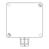
For DIN 1 Rail Mounting
Attach the optional rail
mounting clip (TTC-DRC)
to the base unit and clip
base unit on rail. Remove
the top housing from the
TTC-1. Place one of the
hex nuts in the molded
hex cavity in the center
of the DIN rail plate. Align
the DIN rail plate with
the bottom of the TTC-1
base and insert one of
the screws through the
insulating collar and the hole in the center of the base. Turn the
screw to secure the base. Insert the second hex nut into the
remaining molded hex cavity at the end of the hex plate and use
the second screw to secure the plate.
Figure 3: DIN rail mounting
Installing the TTC-1
WARNING: To avoid electrical shock – all wiring
must be done with the power off.
WARNING: To avoid electrical shock – all wiring
must be done with the power off.
 Loading...