nVent.com | 3
Power Supply Connection
Note: For proper operation of the TTC-1, use a power
supply whose output is electrically isolated from the
incoming AC line power and ground.
One (and only one) TTC-1 can be connected to the output of
one of the following suitable power supplies:
a) a transformer (except an autotransformer)
b) an isolated AC-to-DC switching or linear supply
(use a UL Listed Class II power supply)
c) an isolated DC-to-DC switching power supply
(use a UL Listed Class II power supply)
d) a 15 to 24 V battery
Do not connect either leg of the power supply output to
neutral or ground.
To ensure that multiple TTC-1 modules are isolated from
ground and from each other, each TTC-1 module requires a
separate isolated power supply.
There is no polarity requirement when using a DC power supply.
Maximum wire size: 14 AWG.
Relay Connections
Trouble Relay:
One relay with single pole, double throw contact.
The relay is normally energized. Loss of power at the TTC-1 module
causes the relay to switch to the ALARM condition (COM-NC open).
Leak Detection Relay:
One relay with double pole, double throw contacts.
Leak detection relay latch can be disabled by removing jumper
wire between terminal 18 to 19.
See further discussion in the Field Adjustments and Maintenance
section on page 5.
Note: If relays are connected to automatic equipment,
verify proper operation.
Module Field Adjustments:
Time Delay can be increased from immediate to approximately 2
minutes using adjustment screw on rear panel.
Sensitivity can be increased or decreased from factory setting with
adjustment screw on rear panel.
See further discussions in the Field Adjustments and Maintenance
section on page 5.
WARNING: To avoid electrical shock – all wiring
must be done with the power off.
Final Check List
1. Complete a system inspection in the presence of the owner.
2. Ensure a plan showing the location of the sensor is available.
3. Check that the following information is clearly visible adjacent to the alarm module:
• “In case of alarm” instructions
• Location of the system map in case it is not installed adjacent to the alarm module
• Name and contact number of the person responsible for operating the system
• Supplier’s contact name and address
4. Give these Installation, Operating and Maintenance Instructions to the owner.
5. Make the owner aware that it is strongly recommended to perform a systems check at regular intervals, at least every six (6) months.
TRACETEK
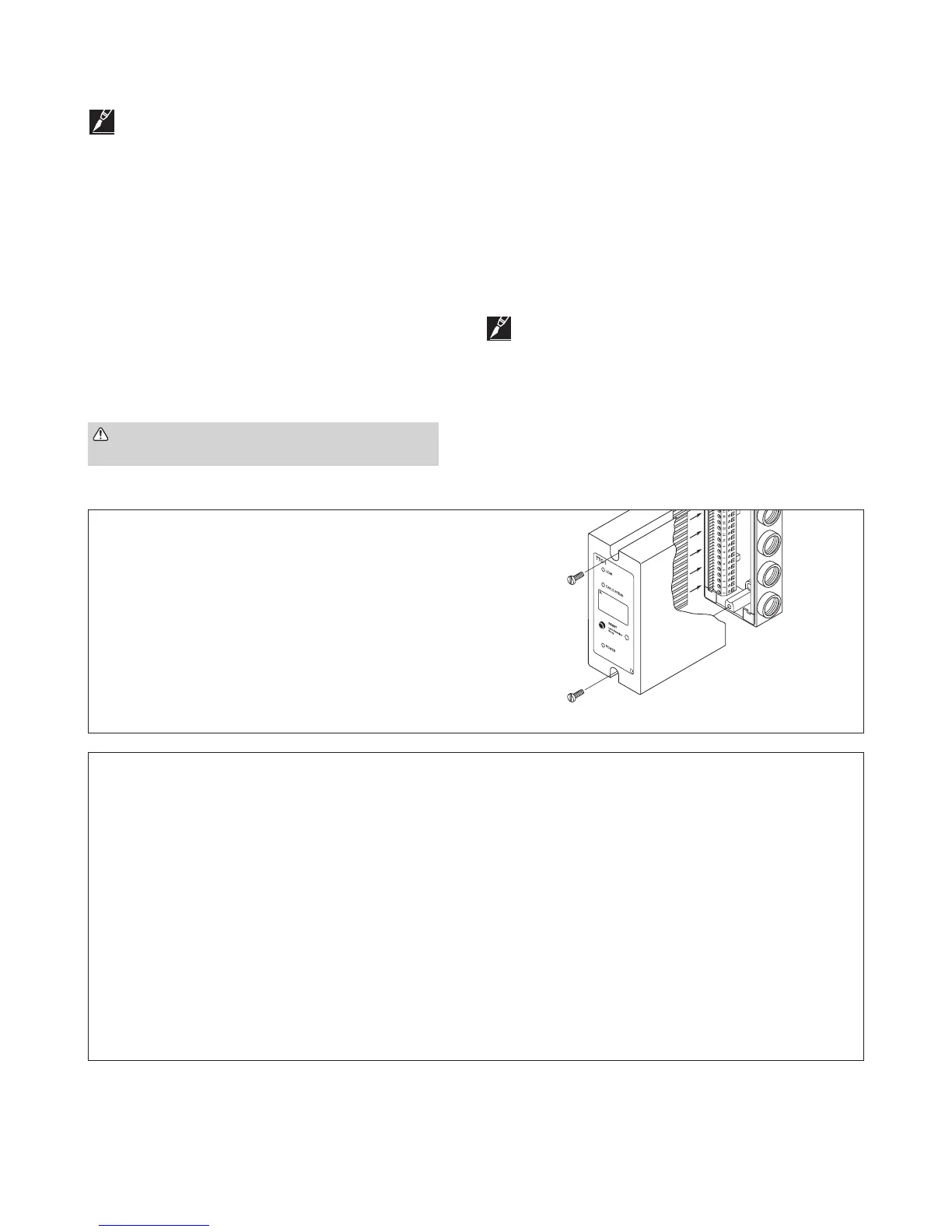
Figure 7: Module reassembly
Final Reassembly
When all wiring connections are complete and the field
adjustments have been made, carefully insert the edge of the
circuit board into the terminal strip edge card connector. Using
a gentle rocking motion, push the circuit board module into the
base unit until it seats.
Use the two captive screws on the module to secure the circuit
module to the base, see Figure 7.
Attach the wall label in a conspicuous place near the TTC-1.
 Loading...