Do you have a question about the RaycoWylie i4500 and is the answer not in the manual?
Provides an overview of the manual's content and safety guidelines for operating the i4500 system.
Details the required qualifications and abilities for personnel operating and maintaining the i4500 system.
Explains the system's purpose as an aid to crane operators and its role in preventing operation outside safe limits.
Describes the i4500 as a computerized monitoring system that helps safe crane operation by tracking loads.
Explains the function of the intermittent and continuous buzzer alarms for approaching or exceeding rated capacity.
Details the use of yellow and red warning lights on the display to signal alarm conditions and required actions.
Identifies and describes the function and location of key components like the display box, I/O interface, and sensors.
Presents a block diagram illustrating the communication network and interconnections between system components.
Lists technical specifications including accuracy, operating temperature, supply voltage, display size, and memory capacity.
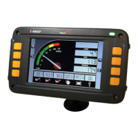
Details the layout and elements of the i4500's default screen display, including load, angle, and radius indicators.
Provides an overview of the display box, including the graphic display, internal buzzer, and warning lights.
Describes the function of each operating button on the i4500 system, such as Mode, Duty, Up, Down, and Escape.
Explains the different operational modes available in the i4500 system, such as Limit Mode, Config Mode, and Diagnostic Mode.
Shows the location of various warning lights and indicators on the i4500 display, such as system error and two-block condition.
Provides detailed explanations for each warning light (approach, overload, lockout) and their associated conditions.
Emphasizes that installation and calibration must be performed by qualified or RaycoWylie certified technicians.
Warns that improper calibration can lead to overloading, machine breakage, tipping, injury, or death.
Outlines critical safety rules and regulations for operating the i4500 system to prevent injury and damage.
Lists residual risks that cannot be avoided despite safety measures, such as lack of power line indication.
Describes the self-test, lockout activation, and duty selection menu that appear when the i4500 system is powered on.
Guides users through configuring the i4500 system, including duty selection and various parameters.
Explains how to select the correct duty number matching the crane configuration for safe operation.
Details the steps for configuring the system when working with the main boom, including boom length, hoist selection, and outriggers.
Guides users through configuring the system for jib operations with a single hoist, including boom length and jib specifics.
Explains configuration for lifting with either the main boom or jib, covering hoist and block configurations.
Describes how to use the Info button to verify the current crane configuration settings for accuracy.
Introduces the system setup mode where display parameters like units, language, date, and time can be configured.
Details how to select measurement units (e.g., feet, tons, meters) for length and load displays.
Explains how to change the display language for the i4500 system, with available languages varying by software version.
Guides on adjusting the system's date and time, crucial for the data recorder function.
Allows selection of screen brightness presets for prevailing lighting conditions, affecting visibility.
Describes how to modify screen brightness levels for optimal readability under various lighting conditions.
Explains how to use Tare Mode to display the actual load on hook by removing the weight of the block, hook, and rope.
Details how to use Bypass/Rigging mode to override alarms or lockout conditions for specific operations like maintenance.
Explains the Rigging Mode used for stowing or erecting the machine, disabling lockout and alarms.
Describes how to enter Rigging Mode by pressing the Bypass/Rigging button when capacity is zero.
Explains how the lockout system can be overridden in overload or ATB conditions, with associated warnings.
Guides on setting custom operational limits like boom angle, height, and radius to enhance safety.
Describes the steps to enter the operational limits setting mode via the Mode button and highlighting 'Limit Mode'.
Details how to adjust the values for operational limits like maximum angle, minimum angle, height, and radius.
Explains how to toggle operational limits between enabled (ON) and disabled (OFF) states.
Introduces the Range Limiting Option, which prohibits crane travel when activated and requires reprogramming if the crane moves.
Details how to access the Range Limiting Mode through the system's menu structure.
Guides on setting a maximum height limit for the boom tip, with a countdown before activation.
Explains how to define a 'Free Zone' limited by side walls, preventing boom movement beyond these boundaries.
Describes how to set a height limit that varies based on the boom's rotation position.
Details setting a radius limit that changes according to the boom's position on rotation.
Explains how to navigate to the diagnostic menu to check system and sensor status.
Details how to view software version and calibration state for angle sensors to aid in diagnosis.
Guides on checking software version, calibration state, and basic criteria for load sensor proper functioning.
Explains how to check the status of relays and digital inputs/outputs on the i4500 relay interface cards.
Describes how to check slew sensor (rotation interface) software version and diagnose issues.
Explains how to view the addresses of sensors detected on the CAN network by the i4500 system.
Lists common error messages, their execution process, and potential causes for internal and external peripherals.
Outlines daily checks to be performed at the beginning of each shift, including alarms, configuration, and system status.
Details inspections to be conducted at regular intervals (every 6 months), focusing on cables, connectors, and the ATB switch.
Provides instructions for performing a rated load test to verify system accuracy and alarm functions.
Covers preventive maintenance, cleaning instructions, and important precautions regarding moisture and pressure steam.
Lists safety precautions to be taken before starting any repairs or adjustments on the crane and system.
Advises on correcting hazardous conditions, performing adjustments according to tolerances, and contacting service.
| Brand | RaycoWylie |
|---|---|
| Model | i4500 |
| Category | Construction Equipment |
| Language | English |