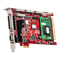
This document describes the RAYLASE SP-ICE-1 PCI PRO Control Card, a versatile control card designed for laser scanning applications. It can operate as a PC-version or a stand-alone unit, featuring RAYLASE's advanced scanning technology.
The control card integrates a complete processor system for real-time scan head and laser control. It receives marking vectors from a PC, stores them, and then controls the scan head and laser accordingly once processing is enabled. This real-time control is maintained even if the host PC is not a real-time system or if the control card is operating in a stand-alone configuration. The card provides a laser modulation signal (LM) and other signals to control YAG or CO2 lasers, with optional ports for customization.
Hardware Features:
- Real-time Processor: An on-board real-time processor ensures precise synchronization of scanning movement and laser control.
- PCI Bus: PCI bus-based with Plug-and-Play functionality.
- Stand-alone Operation: Can be used outside of a PC via an RS-232 interface (up to 115 kBaud) for external downloads.
- Programmable Laser Control: Offers programmable laser control signals for common lasers (e.g., Nd:YAG, CO2).
- Scan Head Interface: Compatible with XY or XYZ scan heads using XY2-100- and XY2-100-Enhanced-Standard.
- Laser Signal Polarity: Selectable polarity for laser signals.
- Pulse Control: Separate control for standby pulse frequency and pulse width.
- Analog Outputs: Two on-board analog ports for controlling lamp current or pulse intensity (0V to 10V, 8-bit resolution).
- Digital I/O: Includes 3 buffered digital outputs and 12 buffered digital inputs, with optional additional I/O capabilities.
- Encoder Interface: Integrated encoder interface for Marking-On-The-Fly (MOTF) applications, allowing for editing moving objects.
Software Features:
- DLL Driver: DLL driver software for Windows® Vista/Win 7.
- Double Buffer Concept: Supports over 1,000,000 commands per list.
- Simultaneous Processing: Allows simultaneous processing of the current list while downloading new commands to the next list.
- Scalable Output: Scalable output of new data with 1µs resolution.
- Output Interval: Shortest possible output interval of 20µs (variable in 1µs steps).
Options:
- MOTF Add-on Card: An add-on card is available for enhanced MOTF functionality.
- Master-Slave Option: For high throughput, up to 4 scan heads can be combined with one laser using the master-slave option.
- Master-Master Operation: Enables minimum process time and maximum flexibility, allowing independent control of up to 4 lasers and scan heads.
- Stand-alone Option: Available for driving the scan head and laser without a PC.
Technical Specifications:
Dimensions and Weight:
- Dimensions: W = 106mm, L = 188mm
- Weight: 155g (with on-board processor), 137g (without on-board processor)
Environmental Conditions:
- Ambient temperature: +15°C to +35°C
- Storage temperature: 0°C to +80°C
- Humidity rel.: ≤80% non-condensing
Minimal System Requirements:
- Processor: Intel Pentium or compatible
- Operating systems: Windows® XP/ Windows® Vista/ Windows® 7
- RAM: 1GB recommended
- Graphic card: VGA (16Bit)
- Extension slot: One to four PCI slots, depending on configuration
- Free hard disc memory: Minimum 30MB
Scan Head Interface (J1 - 25 PIN D-SUB):
- Diff.Input-, Diff.Input+:
- Input Voltage: -4 to +8V
- Input Threshold: max. 200mV
- Diff. Input Voltage: max. 5V
- Hysteresis: typ. 70mV
- Diff.Output-, Diff.Output+:
- Output low: max. 0.5V, max. 40mA
- Output high: min. 2.0V, max. 40mA
Port C, Laser / I/O Interface (J2 - 9 PIN D-SUB):
- TTL Input24V:
- Input low: max. 1.3V
- Input high: 1.6V to 24.0V
- Hysteresis: typ. 1.1V
- Input impedance: approx. 3KΩ
- ESD protection: ± 10kV
- Analog Output:
- Amplitude: 0V to +10V ± 1%
- Output current: 5mA max.
- Bandwidth: 1kHz
- DAC resolution: 16Bit
- Noise ratio (≤1 GHz): 60dB min.
- TTL Outputs:
- TTL low: 0.5V max., max. 4mA
- TTL high: 3.84V to 5.0V, max. 4mA
- TTL hc Outputs:
- TTL low: max. 0,5V, max. 40mA
- TTL high: min 2V, max. 40mA
RS-232 Serial Interface (I3 - 10PIN ITC):
- Used as a communication interface for stand-alone applications.
- Data transmission rate: 115.2kBaud.
- Requires RS-232 serial interface DLL-drivers installed on the host PC.
Laser Control Interface (I8 - 26PIN ITC):
- Analog Output:
- Amplitude: 0V to +10V ±1%
- Output current: max. 5mA
- Bandwidth: 1kHz
- DAC resolution: 16 Bits
- Noise ratio (≤1 GHz): min. 60dB
- TTL Outputs:
- TTL low: max. 0.5V, max. 4 mA
- TTL high: 3.84 to 5V, max. 4 mA
- TTL Input 24V:
- Input low: max. 1.3V
- Input high: 1.6 bis 24.0V
- Hysteresis: typ. 1.1V
- Input impedance: ca. 3KΩ
- ESD protection: ±8kV
- Diff.Output-, Diff.Output+:
- Output low: max. 0.5V, max. 40mA
- Output high: min. 2V, max. 40mA
Interface for Marking-On-The-Fly-Option (MOTF) (X300):
- Allows marking objects in motion by adapting the marking process to actual motion based on moving information.
- MOTF signals are transferred via a 9-pin Sub-D male connector on a slot bracket.
- Equipped with differential inputs, supporting both differential and single-ended input signals.
- Evaluates signals A and B, doubling resolution compared to previous versions.
- Specifications:
- Threshold: min. -200mV max. 200mV differentially at -7V to +12V Common-mode voltage
- Input frequency max.: 250kHz
- Recommended input level: Low: 0.5V High: 3V (each +A and -A respectively +B and -B opposing)
- Input impedance: 120Ω
- Inputs, ESD protection: ≥ 6.5kV
- Output current: VDD +5V for position encoder can supply 0.2A max.
Voltage Supply (I9):
- For stand-alone mode, the SP-ICE-1 PCI PRO control card must be supplied with voltage via connector I9.
Status LEDs:
- D1 (red, LM): On if the laser modulation output signal is active.
- D2 (yellow, STOP_MARK): On if the input signal STOP_MARK is set.
- D3 (yellow, START_MARK): On if the input signal START_MARK is set.
- D4 (yellow, REMOTE_EXE): On if the output signal REMOTE_EXE is set.
- D5 (yellow, MIP): On if the output signal Mark_In_Progress is set.
- D6 (green, ADV): On while the on-board CPU reads or writes data to output logic, during processing vector data and I/O operation.
- D7 (green, Power LED): Glows dimly during on-board processor startup and if an unsuccessful startup occurred; glows steadily during regular operation.
Usage Features:
Configurations:
- Master-Master Configuration: Up to four SP-ICE-1 PCI PRO control cards can be run in one PC to independently control up to four RAYLASE scan heads. Each card controls one scan head and one laser, with its own correction file. The
Set_Active_Card command switches between cards.
- Master-Slave Configuration: Up to four SP-ICE-1 PCI PRO control cards can be interconnected via a data bus for synchronous control of up to four RAYLASE scan heads. The master card (with an on-board processor) controls the first head, laser modulation, and timing. Slave cards do not require an on-board processor and each has its own correction file, ensuring synchronous execution.
- MOTF Configurations: An internal MOTF function can be activated via a jumper (J300). If this jumper is set, Port E cannot be used. Without the jumper, an external RAYLASE MOTF card can be used.
Installation Procedures:
- Preparation: Ensure all laser safety requirements are met. Be aware of electrostatic discharge risks when handling components.
- Driver Installation: Install drivers for Windows® XP/ Vista/ 7 from the provided CD.
- Standard Mode Installation:
- Switch off and disconnect the PC.
- Open the PC housing.
- Plug the SP-ICE-1 PCI PRO control card into a free PCI slot and secure it.
- Close the housing.
- The card will be detected and set up automatically upon PC boot.
- Master-Slave Mode Installation:
- Switch off and disconnect the PC.
- Open the PC housing.
- Plug SP-ICE-1 PCI PRO control cards into free PCI slots and secure them.
- Connect the cards via a backplane adapter (dual or quad available).
- Close the housing.
- The cards will be detected and set up automatically upon PC boot.
- Master-Master Mode Installation:
- Install the first SP-ICE-1 PCI PRO control card as per standard mode.
- For subsequent cards (up to three more):
- Shut down and switch off the PC.
- Disconnect the PC from the mains supply and open the housing.
- Insert the next SP-ICE-1 PCI PRO control card.
- Restart the PC; the card(s) will be detected and set up automatically.
- After all cards are installed, run "SP-ICE Config" (SpiceCfg.exe) to select the total number of installed control cards.
- Stand-Alone Mode: Contact RAYLASE staff for support.
Maintenance Features:
Troubleshooting:
- PC not booting:
- Check if the control card is properly mounted in the PCI slot.
- Ensure no metallic parts fell into the PC housing during installation.
- Verify all connectors are properly connected.
- SP-ICE-1 PCI PRO not responding:
- Check Device Manager for "SP-ICE-1 PCI PRO Serial Port" and "SP-ICE-1 PCI PRO Parallel Port" under "Ports (COM & LPT)".
- Install or reinstall drivers from the installation CD if necessary.
- Ensure the control card is correctly inserted by uninstalling and reinstalling it with the PC turned off.
- Update drivers via Device Manager.
- Verify SP-ICE-1 PCI PRO control card drivers/DLL are installed (version 12.8.74.0 or later). Uninstall old drivers and install new ones if needed.
- Ensure only one application accesses the SP-ICE-1 PCI PRO card(s) at a time. Quit other applications and run only one.
- If an application program error is suspected, close all applications and test the card with SpiceCfg.exe.
- Failure in application software:
- Check if the application calls the correct SP ICE.DLL.
- Verify no old version of SP-ICE.DLL is in the application directory or search path.
- Ensure function calls are properly integrated; refer to the RAYLASE "commands and functions" handbook.
- Control of scan head fails:
- Check for proper connection and cable between scan head and control card.
- Verify the scan head is supplied with correct voltage/current (refer to scan head manual).
- Check for application software faults using QUICKTEST.EXE.
- WARNING: QUICKTEST.EXE controls the scan head and laser. Never look into the laser beam or expose any body part to it, as reflections can cause serious injuries.
- Control of laser fails:
- Check for correct interface between the control card and the laser.
- Verify delays are set correctly.
- Ensure the laser and its mode are properly set with the
Set_Mode command.
- If problems persist, contact RAYLASE customer service.
Warranty:
- Governed by RAYLASE AG's general business conditions.
- An authorization number from RAYLASE is required before returning products.
- Product must be packed in original or equivalent protective packaging.
- Warranty is void if unauthorized persons attempt repairs, modify the product, use it improperly, connect it to incompatible devices, or if the warranty period has expired.
- No implicit guarantee or warranty of suitability for specific purposes is made. RAYLASE is not responsible for damages from product use. Separate warranty conditions may apply to individual assemblies.
Laser Safety:
- Customers are responsible for maintaining a laser-safe working environment and for CDRH certification (for OEM customers).
- CAUTION: Always switch on the PC or stand-alone SP-ICE-1 PCI PRO control card before switching on the laser system to prevent uncontrolled laser action.
- Carefully check your application; faulty software can lock up the system, leading to loss of control over the laser or scan head.