Do you have a question about the Raymarine Ray 152 and is the answer not in the manual?
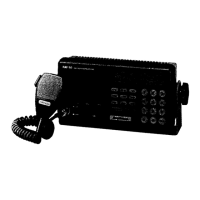
Overview of the RAY 152 Marine Radiotelephone, its features, and benefits.
Details the key features and capabilities of the RAY 152 Radiotelephone.
Technical specifications including frequency range, channels, and power.
Lists the items included with the RAY 152 Radiotelephone package.
General operating principles and capabilities of the RAY 152 SSB Radiotelephone.
Description of the controls, buttons, and indicators on the RAY 152 unit.
Details the connectors and ports located on the rear panel of the unit.
Step-by-step instructions for various operating modes and functions.
Information on the AC 152 Antenna Coupler and its integration.
Describes the function and operation of the noise cancelling microphone.
Instructions for manually entering radio frequencies using the keypad.
Procedure to retrieve stored radio frequencies from memory.
How to scan through stored memory channels.
Information on using ITU standard radio channels.
Explanation of various keypad functions like CLAR, NB, SQ, RF.
Discusses the available SSB radiotelephone services.
Guidance on initiating radio communication and making calls.
Outlines FCC regulations and requirements for marine radiotelephone operation.
Steps for registering with a coast station for communication.
Overview of different marine radiotelephone services.
Procedures for sending distress, urgency, and safety messages.
Information on accessing weather broadcasts.
Explanation of HF radio wave propagation factors.
Requirements and procedures for maintaining a radiotelephone log book.
The international phonetic alphabet used for clear communication.
General guidelines and considerations for installing the RAY 152.
Instructions for properly mounting the main transceiver unit.
Advice on choosing the optimal location for the antenna system.
Guidance and best practices for installing the antenna coupler.
Detailed instructions for making correct electrical connections.
Importance and methods of RF bonding for antenna system performance.
Guidelines for connecting and insulating the antenna lead-in.
Procedures for verifying the installation and system functionality.
Overview of the RAY 152's internal block diagram and major components.
Explanation of the frequency synthesizer's operation and architecture.
Description of the transceiver unit's functional blocks and signal paths.
Details the REF/DDS unit and its role in frequency generation.
Explains the LOOP I Unit and its contribution to frequency synthesis.
Details the RF Tune Unit and its function in tuning circuits.
Describes the IF Filter Unit and its role in signal filtering.
Explains the IF Amplifier Unit and its function in signal amplification.
Details the Power Amplifier Unit and its operation.
Describes the Low Pass Filter Unit and its signal filtering capabilities.
Explains the Audio Frequency Amplifier Unit and its function.
Details the CPU Unit, its program, and control functions.
Describes the Display Unit and its operation on the front panel.
Explains the function and operation of the AC 152 Antenna Coupler.
Introduction to maintenance and repair procedures for the RAY 152.
Recommended monthly maintenance tasks for optimal performance.
Step-by-step guide for tuning up the RAY 152 unit.
Lists the essential test equipment required for maintenance tasks.
Describes the proper hookup of test equipment for procedures.
Procedures for adjusting key transmitter parameters.
Procedures for adjusting receiver performance parameters.
Steps for adjusting the frequency synthesizer for accuracy.
General approach to diagnosing and resolving equipment issues.
Detailed procedures for troubleshooting specific subsystems.
Troubleshooting specific issues related to the power supply.
Troubleshooting the microprocessor and control circuitry.
Troubleshooting steps for the synthesizer subsystem.
Troubleshooting the transmitter section of the unit.
Troubleshooting the receiver section of the unit.
Troubleshooting the antenna coupler subsystem.
Introduction to schematic diagrams and component parts lists.
| Brand | Raymarine |
|---|---|
| Model | Ray 152 |
| Category | Cordless Telephone |
| Language | English |