CURRENT TRANSFORMER TESTING: 7 – 0
Current transformers are, in effect, an opposite wound voltage
transformer. This basically means that the largest number of windings are
on the “X” (low current) side of the current transformer.
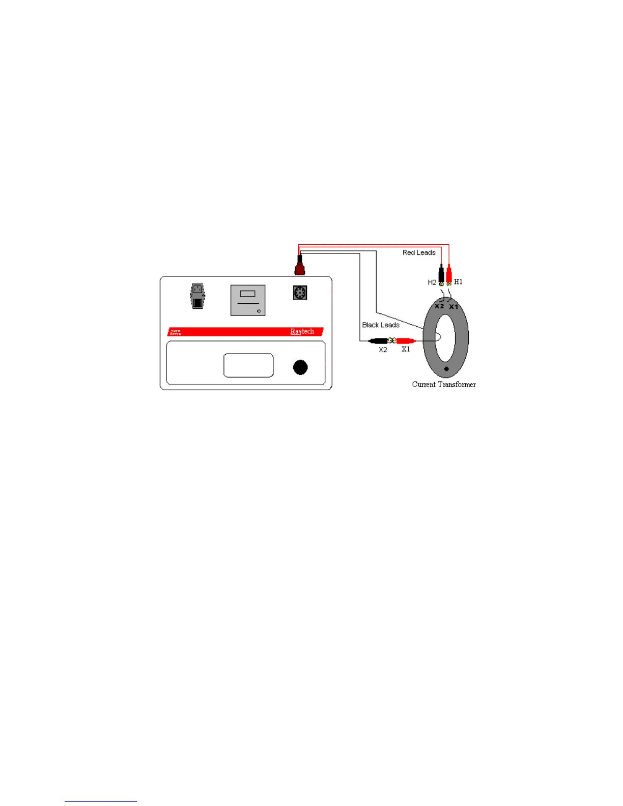
The TR-1 & TR-1P apply a test voltage from 1 …5 V to the “H” leads
and measures back through the “X” leads. The “X” leads must always a
have lower voltage than the “H” leads or an error will be displayed.
Therefore, when testing Current transformers, the “H” leads are
connected to the “X” terminal of the Current Transformer.
In certain cases where the impedance (inductance) of the CT is lower
than the power available from the TR-1 & TR-1P a result indicating an
“Over Current” error will be displayed.
Tapped Secondary CT:
Current transformers with multiple secondary taps are easily tested. After
each specific ratio is tested the H2 lead can be moved to the next position
and that ratio can then be tested.
All rights reserved. No portion may be reproduced without written consent
11 RAYTECH Switzerland