Graphics contained within this publication are for representation only.
5
Chapter 1: Connections and Setup
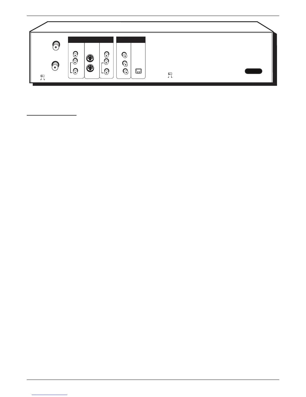
Back of the DVD/VCR
The back of your recorder might look a little overwhelming at fi rst. This section explains what goes where and why. There are two sets of jacks on the back of your DVD/
VCR—INPUT jacks and OUTPUT jacks.
Each jack is explained individually below, but the basic idea is about sending and receiving information to be played on or through your DVD/VCR and displaying that
information on your TV screen.
INPUT The cables connected to the INPUT jacks bring pictures and sound INTO the DVD/VCR, such as the cable signal (programming) from the cable company or
satellite programming from a satellite receiver.
OUTPUT The cables connected to the OUTPUT jacks are sending pictures and sound from the DVD/VCR OUT TO your TV so you can see it on the screen. The correct
cables must be connected to the DVD/VCR’s Output jacks and the corresponding Input Jacks on the TV so you can see the program on the TV. You must also tune the TV to
the correct channel, called a Video Input Channel (for details, go to page 19).
Explanation of Jacks (from left to right)
CH3/Ch4 Switch This switch is also found on VCRs—it corresponds to the TV channel you would use to watch a tape or disc if you only have your TV connected to the
DVD/VCR with an RF coaxial cable via the CABLE/ANTENNA OUTPUT jack (if the switch is set to CH3, you would tune the TV to channel 3). However, the connections
illustrated in the User’s Guide show a preferred connection using audio/video cables or an S-Video cable.
CABLE/ANTENNA INPUT: Connect an RF coaxial cable from an off-air antenna, cable box, or cable outlet to this jack. The cable is sending the programming from the
source to the DVD/VCR.
CABLE/ANTENNA OUTPUT: Connect an RF coaxial cable (provided) to this jack and to the Cable/Antenna Input jack on your TV. It is important to connect this cable
so that your TV receives programming even when the DVD/VCR is turned off.
INPUT: These jacks receive audio and video from a compatible component, such as a satellite receiver. Another set of Input Jacks (INPUT 2) are on the front of the DVD/
VCR for temporarily connecting components such as a camcorder or a video game unit.
VIDEO: Color coded yellow, the video cable you use with this jack provides better quality than an RF coaxial cable but isn’t as good as S-Video. Connect
corresponding video cable to the output jack of a compatible component, such as a satellite receiver or cable box.
AUDIO L (left): Color coded white, connect corresponding audio cable to the output jack of a compatible component, such as a satellite receiver or cable box.
AUDIO R (right): Color coded red, connect corresponding audio cable to the output jack of a compatible component, such as a satellite receiver or cable box.
S-VIDEO
IN: If your satellite receiver or cable box has an S-VIDEO output jack, connect the S-Video cable to this jack because it provides better picture quality than standard
video (the yellow jack).
OUT: If your TV has an S-Video jack, connect an S-Video cable to the TV’s S-VIDEO jack and to this S-VIDEO OUT jack on the DVD/VCR to achieve better picture
quality than standard video (the yellow jack).
continues on next page…
OPTICAL
Y
Pb
ON
OFF
VIDEO
INPUT
OUTPUT
L
R
PROG.
SCAN
AUDIO
VIDEO
OUTPUT
L
R
AUDIO
OUT
IN
Pr
COMPONENT
VIDEO OUTPUT
DIGITAL
AUDIO OUT
S-VIDEO
CABLE/ANTENNA
INPUT
CABLE/ANTENNA
CH4
CH3
DVD/VCR
DVD Playback Only
AC-IN
 Loading...