lIlmOEWmtE w SUPPLY
Yourrange is designedtooperateat a pressure
of4“ofwater column on natuml gas oq ifdesigned
for LPgas (propane or butane), 10”ofwater
columa Make sure you are supplyingyour range
with the type oifgas for which it is designed. This
~ is Conv+%le for use on natural or propane
gas, ti ou dectie to use this range on a different
[
type o gM, conversion adjustments must be
made by a service technician or other qualified
person before attempting to operate the range on
that gas.
For proper opaation, the pressure of natural gas
supplied to the regulator must be between 4“ and
13”of water column. For LP gas, the pressure
supplied must be between 10”and 13”ofwater
column. When checking for proper operation of
the regulator, the inlet pressure must beat least
1“greater than the opemting (manifold)pressure
as “venabove. The pressure re later located
#
r
at e inlet of the range manifol must remain in
the supply line regardless of whether natural or
LPgasis W
7
used A flexible metal appliance
connector use to connect the range to the gas
supply line should have an I.D. of 1/2” and be
5 feet in length for ease of instalktion. In Cana~
flexibleconn@ors must be single wall metal
connectm=sno longer than 6 feet in length.
❑ COHHKI ThE RAH6E 10 ON
Shut off the m@ngas supply valve before
disconnecting the old range and leave it off until
new hook-up has been completed. Don’tforget
to relight the pilot on other gas appliances when
you turn the gas back on.
Because hard piping restricts movement of the
range, the use of an lkGJL+ertified flexible
metal appliance connector is recommended
unlesslocalcodes require ahard-pipedconnection
Never use an old connector when installing a
new range. If the hard piping method is used,
you must careiklly align the pipe; the range
cannot be moved after the connection is made.
To prevent gas leaks, put pipe joint compound
on, or wrap pipe thread tape with Teflon*
around, all mak (external) pipe threads.
YIMloIx Registered trademarkof DuPont
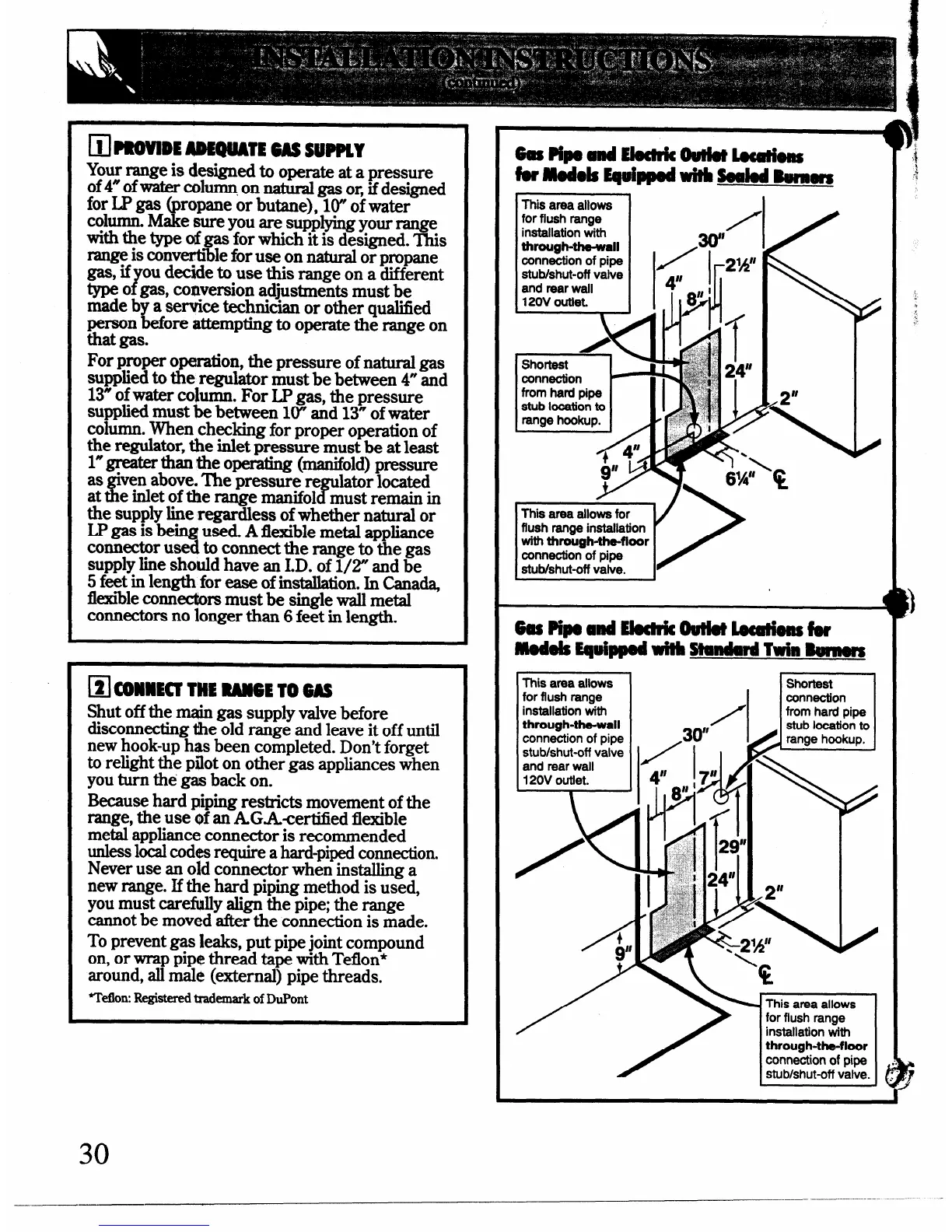
brmodds Equippedwitbsealodkgggfg
ThB area allows
I I
installation with
I
through-the-wall .
,qf’”
for flush range
I
/
1/
conn&tion of pipe
stutdshut-off valve
and rear wall
120V outlet.
Sho~st
connection
from hard pipe
stub location to
range hookup.
y
This area allows for
flush range installation
with through-tha-floor
connection of pipe
stubkhut-off valve.
6as PipeaMubdr&outkHlocathsf8r
models Equipped Wiib standard T* Bunm%
TM area allows
for flush range
installation with
through-the-wall
connection of pipe
stubkhut-off valve
and rear wall
120V outlet.
\
/
.30”
This area allows
installation with
through-the-floor
connection of pipe
stublshut-off valve.
(
,OJIl
I
30
 Loading...