❑ -nw l’HERMGF TOGAS(continued)
1. Installa manual gas line shutdf valve in the
gas line in an easily accessed location outside of
the range. Make sure everyone operating the
range knows where and how to shutoff the gas
supply to the range.
2. Install male 1/2” flare union adapter to the
1/7 WI’ internal thread elbow at inlet of
regulator. On models equipped with dual
burners, installthe male pipe thread end of
the 1/2” flare union adapter to the 1/% NIT
internal thread at inlet of pressure regulator.
Use a backup wrench on the regulator fitting
to avoid damage.
When ins-the range fromthefron~
remove the 90 elbow for easier installation.
3. Install male 1/2” or 3/4” flare union adapter
to the NPT internal thread ofthe manual shut-
offvalve, taking care to back-up the shut-off
valve to keep it from turning.
4. Connect flexible metal appliance connector
to the adapter cmthe ran e. Position range
i
to permit comection at e shut-offvalve.
5. When all connections have been made, make
sure all range controls are in the off position and
turn on the ~ gas supply valve. Use a liquid
leak detector at alljoiits and connections to
check for leaks in the system.
CAUTION: 00 N~
USE A FIAME ‘K)
CHECKFOR GM LEAKS.
When using test pressures greater than 1/2 psig
to pressure test the gas supply system of the
residence, disconnect the range and individual
shut-offvalve from the gas supply piping. When
using test pressures of 1/2 psig or less to test the
W supply sysk~ simply isolate the range horn
the gas supply system by closing the individual
shut-offvalve.
32
.—
1
❑ EIECTRtCU CONIJ~ONS (onsome models)
Electrical Requirements
120vol~ 60 Hertz, properly grounded branch
circuit protected by a K-amp or 2&unp circuit
breaker or time delay fuse.
Extension Cord Cautions
Because ofpotential safety hazards associated
with certain conditions, we strongly recommend
against the use of an extension cord. However,
ifyou still elect to use an extension cord, it is
absolutely necessary that it be a ULlisted,
3-wiregrounding-type appliance extension cord
and that the current carrying rating of the cord
in amperes be equivalent to, or greater than,
the branch circuit rating.
&Wndh9g
IMPORTAN’I’+Please read cardi@)
FOR PERSONALSAFETY,THIS APPLIANCE
MUSI’BE PROPERLYGROUNDED.
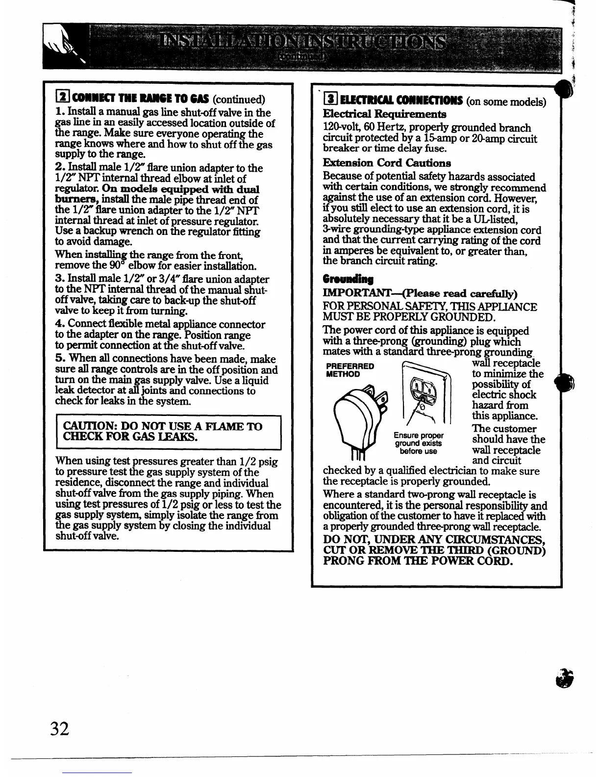
The power cord of this appliance is equipped
with a three-prong (&rounding) plug which
mates with a standard three-prong grounding
PREPERRED
METHOD
Ensure proper
ground exists
before use
waii receptacle
to minimize the
possibility of
electric shock
hazard from
this appliance.
The customer
should have the
wall r~eptacle
and circuit
checked by a qualified electrician to make sure
the receptacle is properly grounded.
Where a standard two-prong wall receptacle is
encountered, it is the personal responsibility and
obligation ofthe customer to have it replaced with
a properly grounded threeprong wallreceptacle.
DO NOT, UNDER ANY CIRCUMSD%NCES,
CUT
OR REMOVETHE THIRD (GROUND)
PRONG FROM T%IEPOWER CORD.
—
_—— ——- ----
 Loading...