PR
ESS
URE
TRANSDUCER
INSERTED
IN
CYLINDER CHAMBER
iiiiiiiiiiiiiiiiiiiiiiiiiiiiiiiiiiiiiiiiiiiiiiiiiiiiiiiiiiiiiiiiiiiiiiiiiiiiiiiiiiiiiiiiiiiiiiiiiiiiiiiiiiiiii RCA WO-33A Cathode-Ray Oscilloscope·
iiiiiiiiiiiiiiiiiiiiiiiiiiiiiiiiiijiiiiii,
iiiiiiiiiiiiiiiiiiiiiiiiiiiiiiiiiiiiiiiiiiiiiiiiiiiiiiiiiiiiiiiiiiiiiiiiiiiiiiiii
VH~RATION
PICKUP
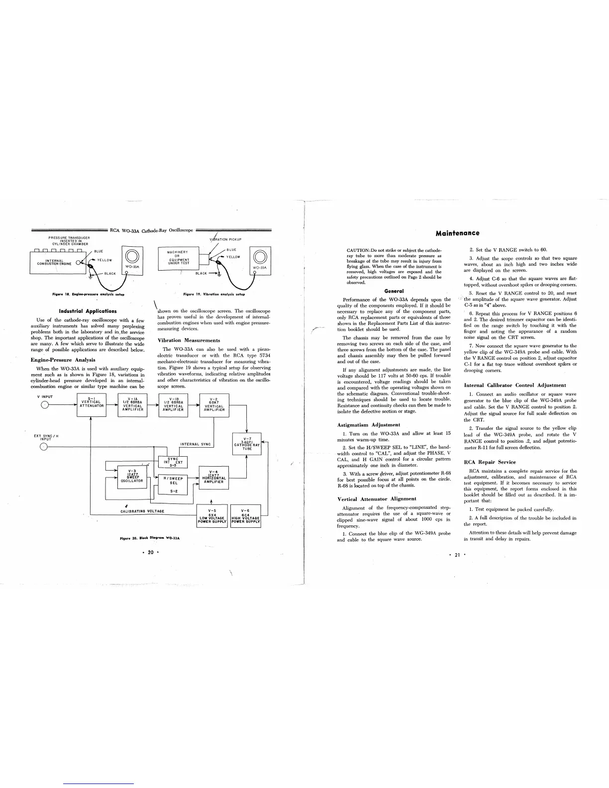
Figure 18. ElIglne-pressure analysis
setup
Industrial Applications
Use
of
the
cathode-ray
oscilloscope
with
a
few
auxiliary instruments has solved
many
perplexing
problems
both·
in
the
laboratory
and
iu;the
service
shop.
The
important
applications of
the
oscilloscope
are
many.
A
few
which
serve
to
illustrate
the
wide
range
of possible applications
are
described
below.
Engine-Pressure
Analysis
When
the
WO-33A
is
used
with
auxiliary
equip-
ment
such
as is
shown
in
Figure
18, variations
in
cylinder-head
pressure
developed in
an
intemal-
combustion
engine
or
similar
type
machine
can
be
V INPUT
S-\
V
-\A
-
VERTICAL
~
1/2
6BR8A
ATTENUATOR
VERTICAL
AMPLIFiER
I'
EXT
SYNC / H
INPUT
L
•
V-3
12AT7
~
SWEEP
OSCILLATOR
-I
MACHINERY
OR
EQUIPMENT
UNDER
TEST
"
Figure 19. Vibration analysis
setup
\shown
on
the
oscilloscope screen.
The
oscillosmpe
has proven useful in
the
development
of internal-
combustion engines
when
used
with engine pressure-
measuring devices.
Vibration
Measurements
The
WO-33A
can
also
be
used
with
a piezo-
electric
transducer
or
with
the
RCA type
5734
mechano-electronic
transducer
for measuring vibra-
tion.
Figure
19 shows a typical
setup
for observing
vibration waveforms,
indicating
relative amplitudes
and
other
characteristics
of
vibration
on
the
oscillo-
scope screen.
V-IB
V-2
~
1/2
6BR8A
~
6BK7
VERTICAL
VERTICAL
AMPLIFIER
AMPLIFIER
Ii
V-7
3AQPI
~
INTERNAL
SYNC
CATHODE
RAY
j
I
TUBE
SYNC
J
-
INT
EXT
S-3
Y-4
!-
~
H /
SWEEP
~
12AT7
HORIZONTAL
SEL
r-
AMPLIFIER
r
S-2
+
CALIBRATING
VOLTAGE
V-5
Y-6
6X4
6C4
I--
LOW VOLTAGE
HIGH
VOLTAGE
,
POWER SUPPLY POWER SUPPLY
Figure 20.
Block
Diagram WO-33A
•
20
•
Maintenance
CAUTION :Do not strike or subject the cathode-
ray tube to more than moderate pressure
as
breakage
of
the tube may result in injury from
Hying
glass. When the case of the instrument is
removed, high voltages are exposed and the
safety precautions outlined on
Page 2 should be
observed.
General
Performance
of
the
WO-33A
depends
upon
the
quality of
the
components employed.
If
it
should
be
necessary
to
replace
any
of
the
component
parts,
only
RCA
replacement
parts
or
equivalents of those
shown
in
the
Replacement·
Farts
List
of this instruc-
tion booklet
should
be
used.
The
chassis
may
be
removed from
the
case
by
removing
two
screws
on
each
side of
the
case,
and
three
screws from
the
bottom
of
the
case.
The
panel
~nd
chassis assembly
may
then
be
pulled forward
and
out
of
the
case.
If
any
alignment
adjustments
are
made,
the
line
voltage
should
be
117 volts
at
50-60 cps.
If
trouble
is
encountered,
voltage readings should
be
taken
and
compared
with
the
operating
voltages shown on
the
schematic
diagram. Conventional trouble-shoot-
ing
techniques
should
be
used
to
locate trouble.
Resistance
and
continuity checks
can
then
be
made
to
isolate
the
defective section
or
stage.
Astigmatism
Adjustment
1.
Turn
on
the
WO-33A
and
allow
at
least 15
minutes
warm-up
time.
2.
Set
the
H/SWEEP
SEL
to
"LINE",
the
band-
width
control
to
"CAL",
and
adjust
the
PHASE,
V
CAL,
and
H
GAIN·
control· for a circular
pattern
approximately
one
inch
in diameter.
3.
With
a screw -priver,
adjust
potentiometer R-68
for
best
possible focus
at
all points on
the
circle.
R-68 is
located
on
top
of
the
chflssis.
Vertical
Attenuator
Alignment
Alignment
of
the
frequency-compensated.
step-
attenuator
requires
the
use of a square-wave or
clipped
sine-wave signal of
about
1000 cps in
frequency.
1.
Connect
the
blue
clip of
the
WG-349A
probe
and
cable
to
the
square
wave
source.
2.
Set
the
V
RANGE
switch
to
60.
3. Adjust
the
scope controls so
that
two
square
waves,
about
an
inch high
and
two
inches
wide
are
displayed
on
the
screen.
4. Adjust
C-6 so
that
the
square
waves are Hat-
topped, without overshoot spikes
or
drooping corners.
5. Reset
the
V
RANGE
control to 20,
and
reset
'.r
the
amplitude of
the
square
wave
generator. Adjust
C-5 as in
"4" above.
6. Repeat this process for
V
RANGE
positions 6
and
2.
The
desired
trimmer
capacitor
can
be
identi-
fied on
the
range
switch
by
touching
it
with
the
finger
and
noting
the
appearance
of a
random
noise signal
on
the
CRT
screen.
7. Now connect
the
square
wave
generator
to
the
yellow clip of
the
WG-349A
probe
and
cable.
With
the
V RANGE control
on
position 2, adjust capacitor
C-l
for a
Hat
top
trace
without
overshoot spikes
or
drooping corners.
Internal
Calibrator
Control
Adjustment
1.
Connect
an
audio oscillator
or
square
wave
generator
to
the
blue
clip of
the
WG-349A
probe
and
cable. Set
the
V
RANGE
control
to
position 2.
Adjust
the
signal source for full scale deHection
on
the
CRT.
2. Transfer
the
signal source to
the
yellow clip
lead of
the
WG-349A probe,
and
rotate
the
V
RANGE
control
to
position .2,
and
adjust
potentio-
meter
R-l1
for full screen deHection.
RCA
Repair
Service
RCA maintains a complete
repair
service for
the
adjustment, calibration,
and
maintenance
of RCA
test equipment.
If
it
becomes necessary to service
this equipment,
the
report forms enclosed in this
booklet should
be
filled
out
as described.
It
is
im-
portant
that:
1. Test
equipment
be
packed
carefully.
2. A full description
oLthe
trouble
be
included
in
the report.
Attention to these details will
help
prevent
damage
in transit
and
delay in repairs.
•
21
•
 Loading...