Operation
To
become familiar with
the
operation of
the
WO-33A Oscilloscope, it
is
recommended
that
the
operator follow
the
procedure outlined below in
the
order
given.
The
section "Function of Controls
and
Terminals" on pages 6
and
7 of
the
block diagram
on
page
20 will also
be
helpful.
Initial
Procedure
1.
Connect
the
power
cord
at
the
rear
of
the
instrument to
an
ac
outlet supplying 105-125 volts
at
50-60 cps.
2.
Turn
the
INTENSITY
control clockwise from
the
"OFF"
position
and
wait a
few
seconds for
the
instrument to
warm
up.
3. Rotate
the
INTENSITY
control farther clock-
wise
until, either a spot or a horizontal line appears
on
the
screen.
The
spot or line should increase in
brilliance as
the
control
is
turned
clockwise.
NQTE:
Do
not allow a small spot of high brilliance to remain
stationary on
the
screen for
an
appreciable length of
time because
discoloratiol'l or
burning
of
the
screen
may
result.
4. Adjust
the
FOCUS
control for
an
image of
maximum sharpness.
5.
Turn
the
H/SWEEP
SEL
control to
the
"H-
IN"
position.
In
this position,
without
an
external
signal
being
applied
to
the
H-INPUT
terminals, no
sweep
voltage,
appears
at
the
horizontal-deflecting
electrodes of
the
cathode-ray
tube
and,
therefore,
only a spot will appea'r on
the
screen,
6.
Position
the
spot in
the
center
of
the
screen
by
adjusting
the
V POS
and
H POS controls.
Vertical-Amplifier
Operation
1. Connect
the
WG-349A
probe
connector to
the
V
INPUT
connector, Set
the
V
RANGE
control
to
"CAL".
The
screen should
now
display a vertical
trace, indicating
that
a signal has
been
applied to
the
vertical-deflecting electrodes of
the
cathode-ray
tube.
2.
Change
the
height
of
the
vertical trace
by
rotating
the
V
CAL
control.
3.
Set
the
H/SWEEP
SEL
to
the
dot
between
15
and
150.
• 8 •
4. Lock in as described
under
"Sweep Oscillator
Operation"
.
Horizontal-Amplifier
Operation
1.
Apply an ac signal of from 1 to 3 volts to
the
EXT
SYNC/H
INPUT
terminal. An audio-frequency
generator
or
a 60-cps line signal
may
be
used
as
the
source.
Set
the
HJSWEEP
SEL
to
"H
IN", set
the
V RANGE control
to
60,
and
set
the
H GAIN
control fully clockwise. A horizontal line will appear
on
the
screen, indicating
that
an
external signal has
been applied to
the
horizontal-deflecting electrodes
of
the
cathode-ray
tube.
2. Disconnect
the
lead
from
the
voltage source.
The
horizontal line will
be
replaced
by
a spot.
3.
Tum
the
H/SWEEP
SEL
to
the
"LINE"
position. A horizontal line should appear. NOTE:
When
the
H/SWEEP
SEL
switch
is
set
to the
"LINE"
position,
part
of
the
power-line signal
is
fed internally to
the
horizontal amplifier, providing a
sinusoidal horizontal-deflection voltage of power-line
frequency.
The
SYNC/PHASE
control can
be
nsed
to adjust
the
phase
of
the
internal sinusoidal sweep.
4.
Turn
the
H/SWEEP
SEL
control
to
any of
the sweep positions.
The
sawtooth
output
from
the
sweep oscillator is
applied
internally to the horizontal
amplifier
and
a linear horizontal trace appears on
the screen.
Sweep-Oscillator
Operation
1.
Adjust
the
H/SWEEP
SEL
and
the
SWEEP
VERNIER control to give a sweep of approximately
power-line frequency. Connect
the
ground lead
from the WG-349A
to
the
ground side
of
an
ac-voltage source. An audio-frequency generator or
a power-line signal can
be
used as a source. With
the cable connector of
the
WG-349A
attached
to the
V
INPUT
connector of
the
WO-33A, connect the
blue lead to the
other
side of
the
low-voltage source.
Adjust
the
SWEEP
VERNIER
control for a single
cycle on
the
oscilloscope screen. Rotate
the
SYNC/
PHASE
control
and
note
that
it
should
be
adjusted
to a minimum position neeessary to lock
pattern
in
a stationary position.
iiiiiiiiiiiiiiiiiiiiiiiiiiiiiiiiiiiiiiiiiiiiiiiiiiiiiiiiiiiiiiiiiiiiiiiiiiiiiiiiiiiiiiiiiiiiiiiiiiiiiiiiiiiiiiiiiiiiiiiiiiiiiiii
..
RCA WO-33A Cathode-Ray Oscilloscope
2.
With
a single
pattern
on
the
scr~n,
notice
whether
the
pattern
drifts across
the
face of
the
tube.
Horizontal
drift
indicates
that
the
SYNC/PHASE
control should
be
rotated toward its clockwise or
counterclockwise limits or
that
the
SWEEP
VERN-
IER
control
should
be
adjusted until
the
waveform
is locked in.
3.
Connect
the
WG-349A connector to an external
signal of a different frequency.
4.
Set
the
H/SWEEP
SEL
control to «H
IN"
and
adjust
the
H/SWEEP
and
SWEEP
VERNIER con-
trols to produce a suitable sweep frequency. Apply
a synchronizing voltage from the external signal to
the
EXT
SYNC terminal. Set
the
SYNC switch to
"EXT".' Adjust
the
SYNC/PHASE control until
the
pattern locks
in
on
the
oscilloscope screen.
Figure
1.
WG-349A
direet/low-capacitance
probe
and
cable
supplied
with
WO-llA
Use
of
the
WG-349A
Direct/Low-Capacitance
Probe
The WG-349A Direct/Low-Capacitance Probe and
Cable is
designed
especially for use with
the
WO-
33A Oscilloscope. This single-unit probe
is
equipped
with two clips
from
the
probe
housing which permits
using
the
probe
for direct measurements or for
connecting a built-in high-impedance network in
series
with
the
test
point
and
the
probe cable. When
the
yellow lead is used,
the
input capacitance of
the
cable
and
scope is reduced to 10
/L/Lf
and
the ,input
resistance
is
raised to 10 megohms. These high-im-
peda'1ce characteristics permit use of
the
WO-33A
in
high-impedance circuits, such as those found in
TV sync-separator
and
video-amplifier stages, which
would
not
operate
properly if loaded down
by
a
conventional
scope
probe
and
cable.
Whenever
the
probe
is
used in its low-capacitance
position, however,
the
signal
is
attenuated by a
factor of ten. Therefore,
when
voltage measurements
• 9 •
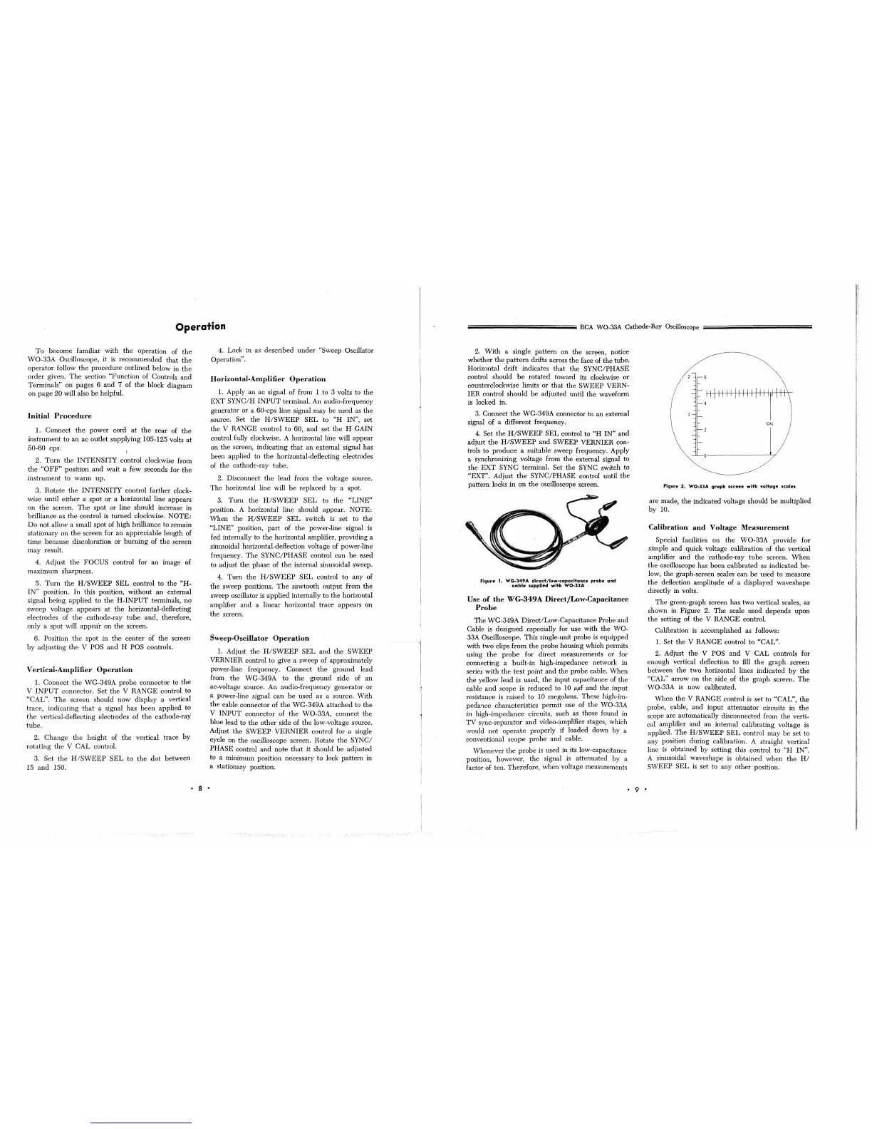
Figure
2.
WO·llA
graph
screen
with
voltage
scales
are made,
the
indicated voltage should
be
multiplied
by 10.
Calibration
and
Voltage
Measurement
Special facilities
on
the
WO-33A provide for
simple
and
quick voltage calibration of
the
vertical
amplifier
and
the'
cathode-ray
tube
screen.
When
the
oscilloscope has
been
calibrated as indicated be-
low,
the
graph-screen scales can
be
used to measure
the
deflection amplitude of a displayed waveshape
directly
in
volts.
The
green-graph screen has two vertical scales, as
shown
in' Figure 2.
The
scale used depends
upon
the setting
of
the
V RANGE control.
Calibration
is
accomplished as follows:
1.
Set
the
V RANGE control to "CAL".
2. Adjust
the
V POS
and
V
CAL
controls for
enough vertical deflection to fill
the
graph
screen
between
the
two horizontal lines indicated
by
the
"CAL" arrow on the side of
the
graph screen.
The
WO-33A
is
now calibrated.
When
the
V RANGE control
is
set to "CAL",
the
probe, cable,
and
input attenuator circuits in
the
scope are automatically disconnected from
the
verti-
cal amplifier
and
an internal calibrating voltage is
applied.
The
H/SWEEP
SEL
control
may
be
set to
any position during calibration. A straight vertical
line
is
obtained by setting this control to
"H
IN",
A sinusoidal waveshape
is
obtained
when
the
HI
SWEEP
SEL
is
set to any other position.
 Loading...