oOiiiiiiiiiiiiiiiiiiiiiiiiiiiiiiiiiiiiiiiiiiiiiiiiiiiiiiiiiiiiiiiiiiiiiiiiiiiiiiiiiiiiiiiiiiiiiiiiiiiiiiiiiiiiiiiiiiiiiiiiiiiiiiiiiiiiiiiiiiiiiiiiii
RCA WO-33A Cathode-Ray Oscilloscope
Calibration
will
hold
for
both
the
wide
band
and
narrow
bandwidth
positions. After calibration,
an
input
signal
may
be
read
directly in peak-to-peak
volts
by
measuring
the
vertical deflection against
the
correct
graph-screen
scale.
Example:
It
is desired
to
simultaneously display
and
measure
the
peak-to-peak voltage
amplitude
of
the
horizontal
driving
pulse
at
the
grid
pin
of
the
horizontal-deflection-output stage in a
TV
receiver.
Procedure
is as follows:
1. Set
the
bandwidth
control to
"CAL"
and
set
the
H/SWEEP
SEL
to
"H
IN".
2.
Adjust
the
V
CAL
control for exactly full
scale vertical deflection as
measured
on
the
graph
screen.
Adjust
the
V POS control so
that
the
bottom
of
the
trace
rests
on
the
base-scale line
and
the
top
of
the
trace
rests
on
the
upper
horizontal line.
3.
The
WO-33A
is
now
calibrated.
4.
Connect
the
ground
lead
from
the
WG-349A
to
the
TV
chassis.
Connect
the
blue
probe
clip to
the
appropriate
tube-socket pin.
5.
Set
the
V
RANGE
control to a position which
gives
the
desired on-screen deflection of
the
wave-
shape.
6. Lock in
the
waveshape
as
described
under
"Sweep Oscillator
Operation".
7. Adjust
the
V
POS
control to position
the
bottom
of
the
trace
on
the
graph-screen
base
line.
8.
Read
the
peak-to-peak
voltage
amplitude
of
the
waveshape
from
the
appropriate
scale on
the
graph-
screen.
The
peak-to-peak
voltage
is
read
from
the
scale
point
opposite
the
top
of
the
waveshape.
NOTE:
If
the
WG-349A
is
used
in its low-capaci-
tance position,
an
attenuation
factor of
10
is
intro-
duced
and
it
will, therefore,
be
necessary
to
multiply
the voltage
reading
by
10 to
obtain
the
correct
peak-to-peak voltage
amplitude.
• 10 •
Applications
Successful servICIng
and
maintenance
of black-
and-white
and
color-television receivers requires
special techniques,
not
usually
employed
in
the
serv-
icing of
other
electronic
equipment.
The
general
complexity
and
variety of circuits
used
in
modem
television receivers requires a
great
deal
of
knowl-
edge
on
the
part
of
the
service technician
and
de-
mands
that
test
equipment
be
used
properly.
The
oscilloscope is
of
especial importance in
the
servicing of color receivers. A good television-service
oscilloscope,
such
as
the
RCA WO-33A, may
be
u5ed in signal
tracing
in every section
of
the
receiver;
the
'scope
may
also
be
used
for
making
peak-to-peak
voltage measurements in such
important
sections of
the receiver as
the
sync
and
deflection circuits
and
in the video, chrominance,
and
luminance sections
of color-TV receivers.
In
alignment work, where
video, chrominance,
and
luminance circuit adjust-
ments must
be
made
to
produce
the
desired wave-
shape,
the
oscilloscope is indispensable.
The
WO-33A
may
be
used
in
all
these
applications.
Signal-tracing
means
tracing
the
television signal
through various sections of
the
television receiver
to
determine
how
circuits
are
functioning in terms
of
the
shape
and
voltage value of
the
waveform. As
the signal passes from one stage
to
another
in
the
receiver,
the
shape
of
the
waveform
may
be altered,
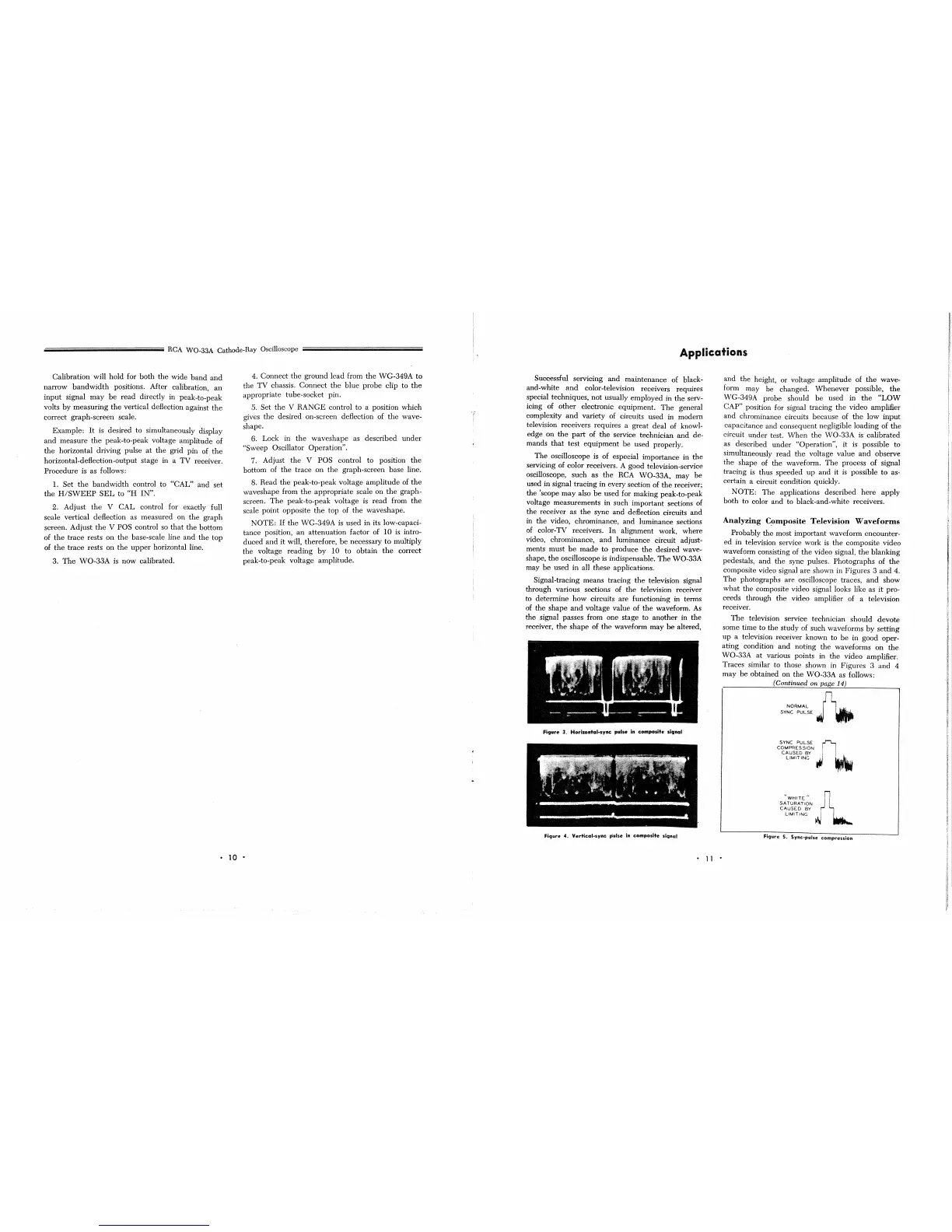
Fi9ure
3.
Horizontal-sync
pulse
in
composite
signal
Fi9ure
4.
Vertical-sync
pulse
In
composite
signal
•
11
•
and
the
height,
or
voltage
amplitude
of
the
wave-
form may be changed.
Whenever
possible,
the
WG-349A probe should
be
used
in
the
"LOW
CAP" position for signal tracing
the
video amplifier
and
chrominance circuits because of
the
low
input
capacitance and
consequent
negligible
loading
of
the
circuit
under
test.
When
the
WO-33A is
calibrated
as described
under
"Operation",
it
is possible to
simultaneously
read
the
voltage value
and
observe
the
shape
of
the
waveform.
The
process
of
signal
tracing
is
thus
speeded
up
and
it
is
possible
to
as-
certain a circuit condition quickly.
NOTE:
The
applications described
here
apply
both
to
color
and
to black-and-white receivers.
Analyzing
C~mposite
Television
Waveforms
Probably
the
most important waveform
encounter-
ed
in television service work
is
the
composite video
waveform consisting of
the
video signal,
the
blanking
pedestals,
and
the
sync pulses.
Photographs
of
the
composite video signal
are
shown in
Figures
3
and
4.
The
photographs
are
oscilloscope traces,
and
show
what
the composite video signal looks like as
it
pro-
ceeds through
the
video amplifier of a television
receiver.
The
television service technician should
devote
some time to
the
study
of such waveforms
by
setting
up
a television receiver known to
be
in
goodoper-
ating
condition
and
noting
the
waveforms
on
the
WO-33A
at
various points in
the
video amplifier.
Traces similar to those shown in Figures 3
and
4
may
be
obtained
on
the
WO-33A as follows:
(Continued on page 14)
NORMAL
fl,
..
SYNC
PULSE
J •
SYNC
PULSE
~
COMPRESSION
CAUSED
BY
JJ
LIMITING
'it'
"WHITE"
'l
SATURATION
CAUSED
BY
LIMITING
~
Figure 5. Sync-pulse
compression
 Loading...