DCN: 141-00240-02 7/03 4
Installation
Install the controller near the HVAC mechanical system or in a convenient indoor service location, such as the
garage, basement, closet or utility room.
Mount the controller to the wall or structural bracing. Mounting the controller onto the HVAC unit is possible but
generally not desirable due to the potential for excessive vibration and heat.
Wiring
Thermostats. Use standard 18GA thermostat wiring to connect the thermostats to the controller and the
controller to the mechanical system.
Dampers. Zone damper outputs provide 24VAC at 1 Amp maximum to the dampers. Use 18 gauge thermostat
wire for the dampers.
Power
ZC2S Control Units are powered from the HVAC system’s 24VAC R and C (common) terminals. No external
transformer is required. Total damper draw must be limited to 1 Amp per zone.
Fuse
The controller is supplied with a 2AG style 2 Amp fuse.
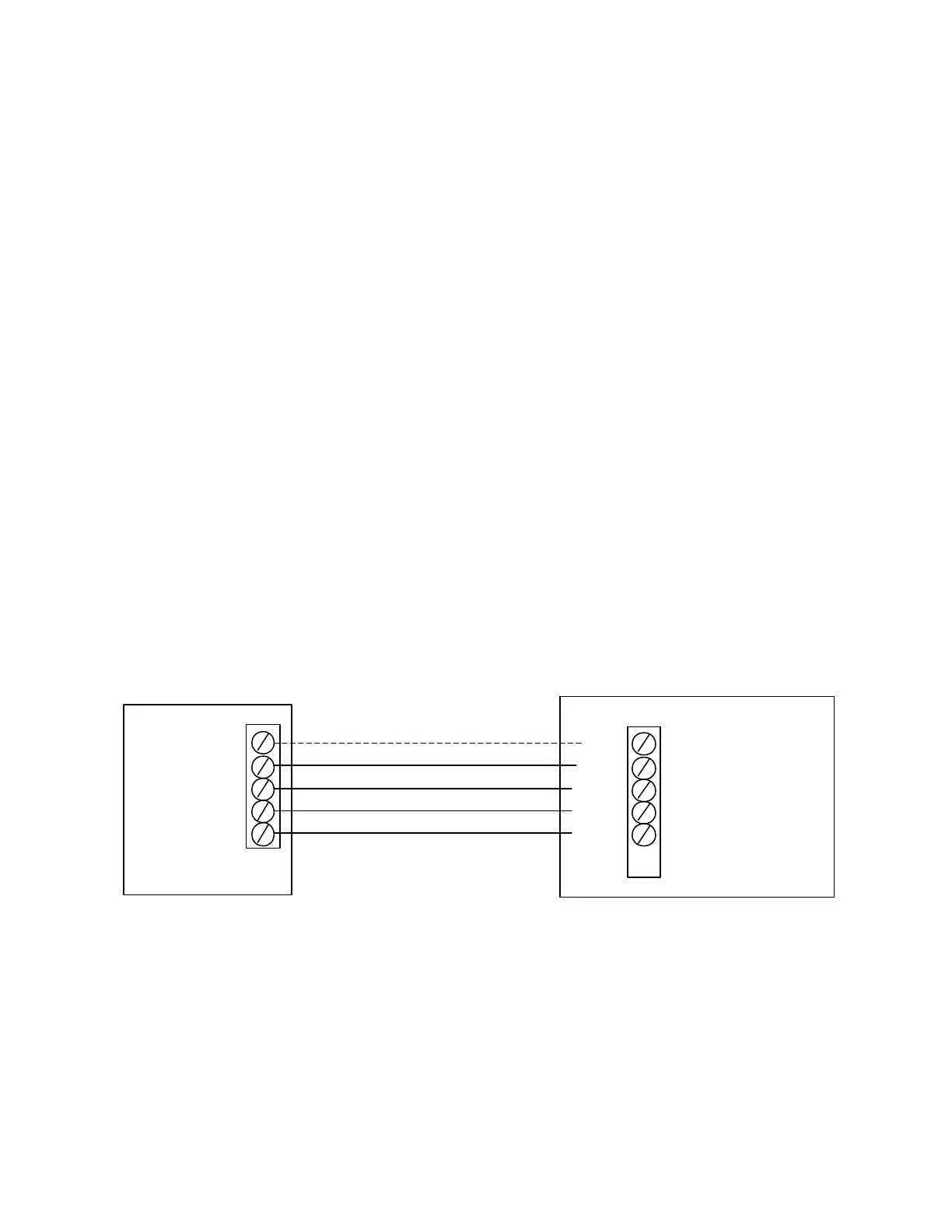
Thermostat Wiring
Connect the zone thermostats to their respective zone input terminals, J1 & J2. Both the 24VAC Common (C)
and 24VAC (R) power is available at these terminals. Only the 24VAC (R) terminal is required for proper input
from the thermostats. The 24VAC Common (C) is provided for thermostats that require power from the system.
ZONE 1 THERMOSTAT
24VAC COM C
24VAC R
HEAT W
COMP Y
ZC2S CONTROL UNIT
24V C
24V R
HEAT W
COMP Y
OPTIONAL FOR POWER IF REQUIRED
FIG 1. WIRING THERMOSTATS TO THE CONTROLLER
 Loading...