DCN: 141-00240-02 7/03 5
HVAC System Wiring
The ZC2S control units connect to the HVAC mechanical systems at the normal thermostat connections on the
HVAC indoor units.
WIRING FOR STANDARD HVAC SYSTEMS
Control Unit Setup: Dipswitch Settings
The control unit has a configuration dipswitch, SW1. Set the dipswitch as follows.
SW1 Position 1: Test Mode (For service technician use only, do not run in test mode)
Select OFF for Normal operation. All delays normal.
Select ON for Test mode to reduce delays to 10 seconds and shorten run times to one minute to facilitate
system checkout and troubleshooting.
SW1 Position 2: Fan Mode Select
Select OFF for Standard Gas systems (no fan with heat calls)
Select ON for Electric Heating systems (fan with heat calls)
SW1 Position 3& 4: Thermal Equalizer Mode Select
These two dipswitch positions determine the length of time the equalizer cycle will run after it has been tripped on
by the Heat Run Time timeout.
C 24VAC COM
R 24VAC
G FAN
W HEAT
Y COMP
R 24VAC
G FAN
W HEAT
Y COMPRESSOR
YELLOW
INDOOR
FURNACE UNIT
OUTDOOR UNIT
“COMPRESSOR”
Y COMP
C 24VAC COM
ZONE CONTROL
UNIT
Standard Thermostat
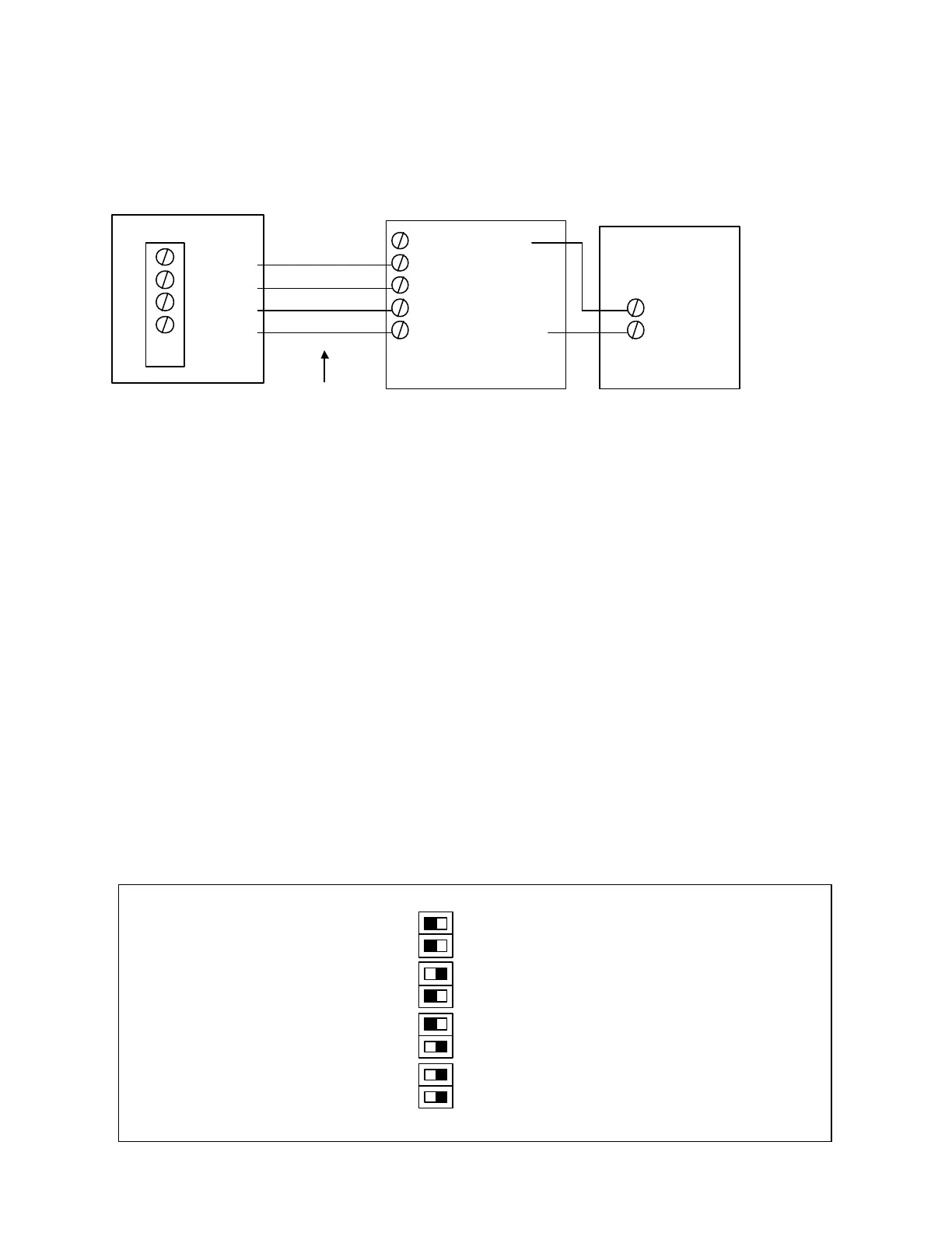
FIG 2. WIRING ZONE CONTROL UNIT TO STANDARD HVAC SYSTEM
OFF ON
3 Off: Equalizer feature Off.
4 Off
3 On Equalizer run time 6 Min
4 Off
3 Off Equalizer run time 8 Min
4 On
3 On Equalizer run time 10 Min
4 On
SW1
FIG 4. DIPSWITCH SW1
EQUALIZER RUN TIME
SETTINGS
ERT1
 Loading...