Do you have a question about the RCT Muirhead 9200 and is the answer not in the manual?
Safety responsibilities and training for personnel involved in installation and testing.
Precautions for machine isolation, operation, and testing to protect equipment and personnel.
Guidelines for product installation, usage, and component handling to prevent hazards.
Introduction to the Muirhead Engine Protection System and its purpose on any machine.
Lists key features and capabilities of the EPS system, including multi-voltage and customisation.
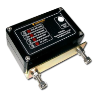
Description of the EPS control unit, its components, and necessary wiring connections.
Explanation of Function 1, typically for coolant level detection with specific delays.
Details on Functions 2, 3, and 4 for monitoring oil pressure, temperature, and oil level.
Explains Alarm Control, Idle Control, and Engine Control (ETR) outputs and their functions.
Steps for mounting the control unit and details on system options like idle timers.
Describes three methods for mounting the audible warning alarm for the system.
Guidance on installing the coolant level sensor in the radiator tank.
Instructions for installing the oil pressure switch in an oil gallery access port.
Steps for installing the engine temperature switch near the thermostat.
Guidance for installing the oil/fuel level switch in tanks or reservoirs.
Process for applying custom labels to the engine protection control enclosure.
List of part numbers and corresponding labels for various alert functions.
Schematic diagram illustrating typical wiring for the 4-function water-cooled system.
Recommended service intervals and general inspection steps for the system.
Maintenance steps for inspecting and refitting the coolant level sensor.
Maintenance recommendations for the oil pressure switch, including replacement intervals.
Maintenance for the engine temperature switch, including replacement advice.
Maintenance for the oil/fuel level switch, including testing procedures.
Steps to perform a system test using the control unit's test switch.
Detailed procedures for testing coolant, oil pressure, temperature, and level sensors/switches.
Lists available decals and wiring looms for the control unit.
Details on various coolant level sensors and oil pressure switches.
Lists temperature switches, oil/fuel level switches, and warning alarms.
Physical dimensions, weight, voltage, and power supply details of the EPS system.
Specifications for input voltage range, spike withstand, and output current ratings.
Recommended tools and usage of a digital multimeter for troubleshooting system faults.
Schematic diagram illustrating ETR Idle Timer, EPS, and Fire Control Unit integration.
| Brand | RCT |
|---|---|
| Model | Muirhead 9200 |
| Category | Protection Device |
| Language | English |