EasyManuals Logo

RD DPS5005 User Manual

RD DPS5005
15 pages
To Next Page IconTo Next Page
To Previous Page IconTo Previous Page
Page #11 background imageLoading...
Page #11 background image
- 11 -
Communication board
fixed screw
Fillister head M3*5
2
Transparent sticky mat
Φ12*4
4
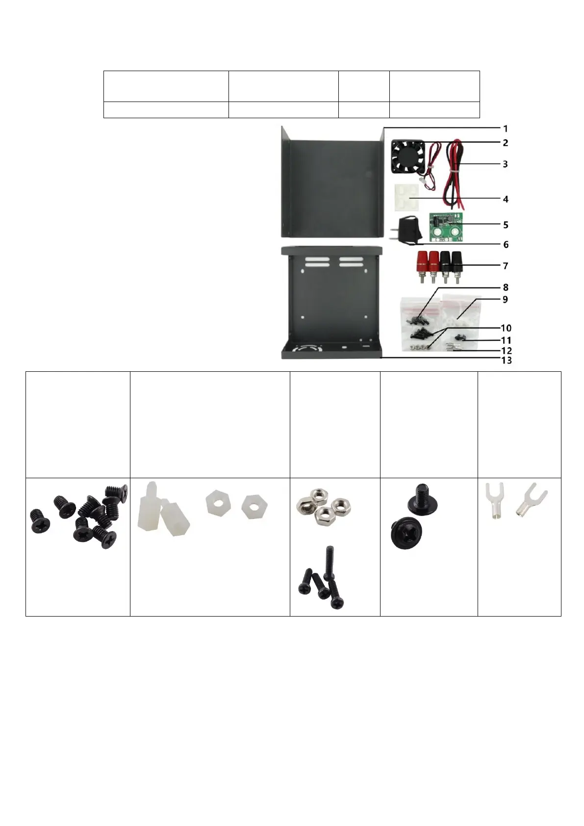
2.3 Kit parts picture
1- Lower cover plate
2- Fan
3- Connecting line
4- Transparent sticky mat
5- Fan power supply board
6- Rocker Switch
7-Binding post
8- Screw for housing
9- Nylon column Nylon nuts
10- Fan fixed screws
11- Communication board fixed screws
12- Cold pressing terminal
13- Upper cover plate
Note:
Screw for housing Flat
head M3*5 8pcs
Nylon column M3 Single head hex
nylon column L=8mm 2pcs
Nylon Nut M3 hexagonal nylon
nut H=2.4mm 2pcs
Fan fixed screw
Fillister
head M3*13 4pcs
Communication
board fixed screw
Fillister head M3*5
2pcs
Cold press
connecting
terminal UT1-4
2pcs
3 Installation Procedures
3.1 Installation Preparation
3.1.1 1 pcs digital control power supply
3.1.2 Tools (Soldering iron, solder, Philips screwdriver, Wire stripping pliers)
3.1.3 A proper installation environment
3.2 Installation Procedures
3.2.1 Use wire stripping pliers to cut proper length line, the length as follows:

Questions and Answers:

Question and Answer IconNeed help?

Do you have a question about the RD DPS5005 and is the answer not in the manual?

RD DPS5005 Specifications

General IconGeneral
BrandRD
ModelDPS5005
CategoryPower Supply
LanguageEnglish

Related product manuals