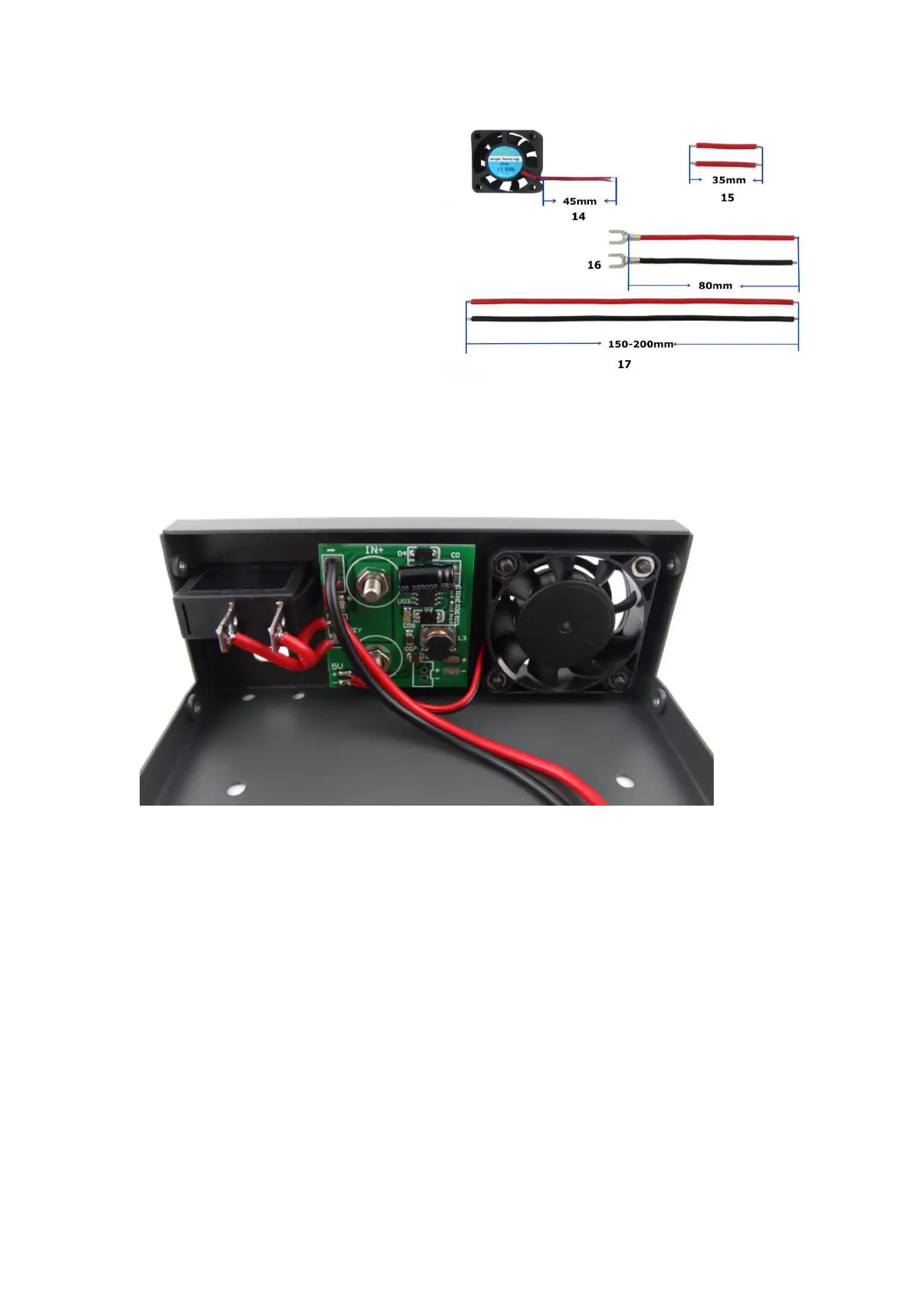
14- Fan line 45mm
15- Switch connecting line 28mm
16- Output connecting line (Cold press
connecting terminal is weld on one side of
line) 80mm
17- Input connecting line 150-200mm
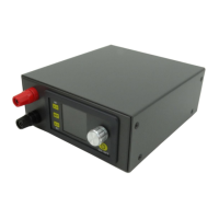
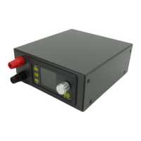
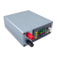
3.2.2 Install the input binding post and switch: put binding post and switch on slot at rear panel.
Install binding post according to rule that red is positive above, black is negative below; and
screw it tightly.
3,2.3 Install fan power supply board:
3.2.3.1 Weld fan line on 5V place at fan power supply board (Note: can’t weld positive and
negative reversely).
3.2.3.2 The power input line welding in the fan power supply board on the upper left corner of
the two pads, pay attention to the positive and negative do not welding the wrong.
3.2.3.3 Install fan power supply board on the binding post (red is positive above, black is negative
below), then use the screw to fix them.
3.2.3.4 Use the prepared wire to weld the power switch on the key place at fan power supply
board,
3.2.4 Install the fan: use the matched screw to fix. The one side attached label is installed
outward.
 Loading...