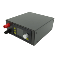
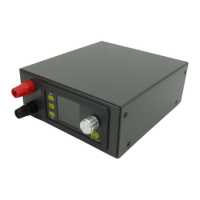
3.2.5 Install the output binding post, and use the output line with cold press connecting terminal
to connect input (red is positive above, black is negative below), and screw it tightly
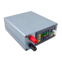
3.2.6 Module connection using pluggable terminal, the input and output of the four threads into
the correct hole in the terminal, and tighten the screw (this process must pay attention to the
four lines do not get wrong)
3.2.7 This step contains power supply installation and USB board installation.