3.2.7.1 Firstly install USB communication board (if you bought no communication version, please
ignore this step). Use nylon column and nylon nut to prop USB board up. Then use the screw to
fix it on preset place of bottom housing
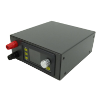
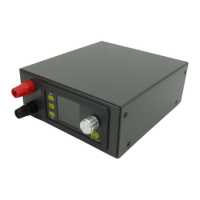
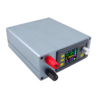
3.2.7.2 Install the power supply module. Please put it on slot at front panel and connect the
connecting terminal (when put it on slot, strength will be proper to avoid the deformation).
3.2.7.3 The input and output connection adopts the pluggable terminals, insert the four wires of
the input and output to the corresponding holes in the Terminal male, then put terminal male
into Terminal female corresponding to IN+ IN- and OUT+ and OUT-.
3.2.7.4 use communication cable to connect USB board with module
3.2.8 After connecting, please power on to check it work or not (before power on, check
connection again)
3.2.9 Install the housing. The upper cover plate will be installed on the upper cover plate. And
then use the screw to fix them
3.2.10 There are 4 transparent sticky mat, you can paste symmetrically them on the 4 corners on
the bottom.
3.3 Internal connection diagram:
 Loading...