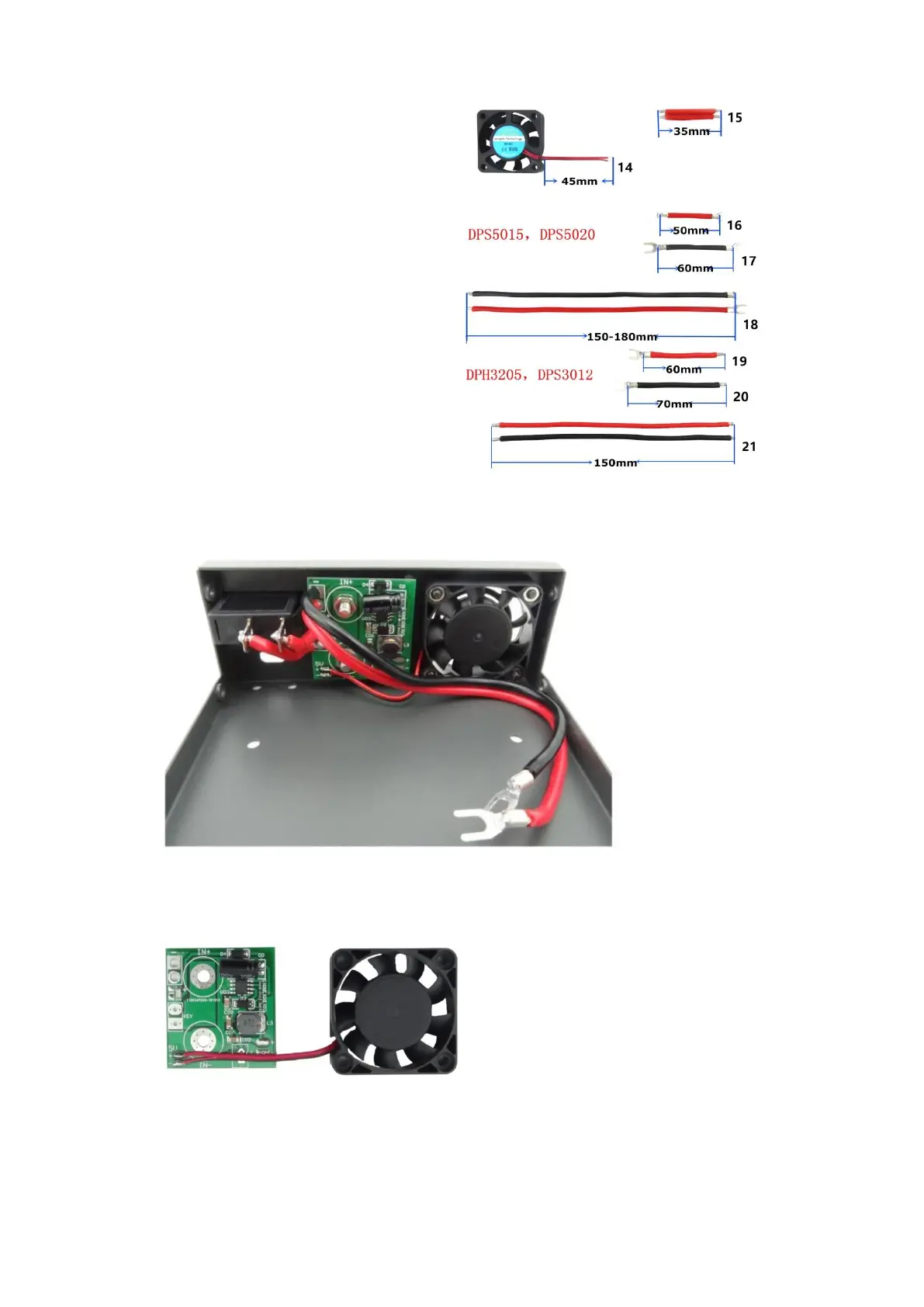
3.2.1 Use wire stripping pliers to cut proper
length line, the length as follows:
14- Fan line 45mm
15- Switch connecting line 35mm
16- Output positive line 50mm
17- Output negative line 60mm
18- Input positive and negative connecting line
150-180mm
19- Output positive line 60mm
20- Output negative line 70mm
21- Input positive and negative connecting line
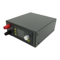
3.2.2 Install the input binding post and
switch: put binding post and switch on slot
at rear panel. Install binding post according
to rule that red is positive above, black is negative below; and screw it tightly.
3,2.3 Install fan power supply board:
3.2.3.1 Weld fan line on 5V place at fan power supply board (Note: can’t weld positive and
negative reversely).
3.2.3.2 The power input line welding in the fan power supply board on the upper left corner of
the two pads, pay attention to the positive and negative do not welding the wrong.
3.2.3.3 Install fan power supply board on the binding post (red is positive above, black is negative