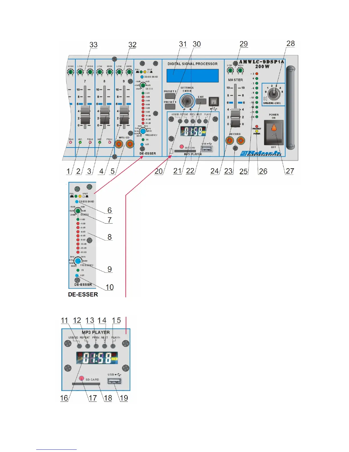
3. Arrangement of elements and sockets.
1- a diode signaling the activity of the particular microphone channels
2- a diode signaling the transposition of a certain microphone channel
3- gain potentiometer in microphone channels
4- gain potentiometer of LINE channel
5- Cinch socket for the external sound source to be plugged in
6- FULL mode switch (full range) or SPLIT (partial band)
7- potentiometer for adjustment damping values
8- damping indicator
9- potentiometer setting lower frequency for mode "SPLIT"
10- AIR button to add high frequencies
11- switch for USB or SD mode
12- repeat
13- previous file
14- next file
15- play file
16- LCD display
17- IR infrared for remote control
18- SD card slot
19- USB slot
20- a pulser to service the function on the display
21- EXIT key exit from the menu
22- USB socket for computer connection
23- Cinch record socket
24- gain sum potentiometer
25- power indicator
26- power and protect LED
27- switch on/ switch off of the amplifier's power
28- 6-pointed zone potentiometer
29- timbre regulation ( bas, soprano ) MASTER
30- preset 1 & 2 switches
31- LCD display
32- timbre regulation ( bas, soprano ) MP3/CD
33- timbre regulation ( bas, soprano ) for microphone channel
3
Mp3 USB/SD player
The view of the front board of the AMWL amplifier..