Re S.p.A. TL01-A
03/07/12 4/13
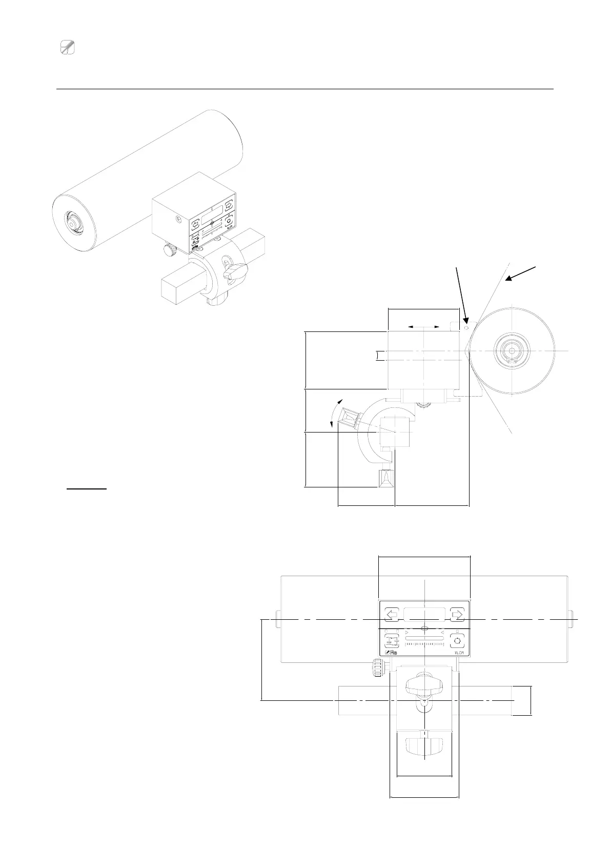
Positioning the TL01-A sensor
47,5 37,5
50
8
64
50
62
±
10mm
2
0
°
±
DIMENSION OF THE “A” BAR :
- standard application: 25mm
- upon request for 1” bars: 25,4mm
material
The spacer, useful to find the correct an
le of
the TL01-A in relation to the roller, must be
positioned between the sensor and the roller,
making sure that the hole is positioned
higher than the TL01-A.
Attention: After having positioned the TL01-
A, the spacer must be removed.
spacer hole
70,5
80
48
60
oA
 Loading...