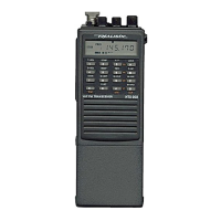
Do you have a question about the Realistic HTX-202 99-1120 and is the answer not in the manual?
Details on operating voltage, temperature range, and general radio parameters.
Defines receiver performance metrics like sensitivity, selectivity, and audio output.
Outlines transmitter performance, including power output, deviation, and current drain.
Step-by-step guide for safely disassembling the radio unit.
Illustrates the main functional blocks and signal flow of the transceiver.
Explains the microphone circuit, transmitter stage, and automatic power control.
Details the VCO, PLL, and loop filter functions for frequency generation.
Covers RF amplifier, mixers, IF stages, and audio/squelch circuits.
Describes the CPU's role in managing functions, power, and CTCSS/DTMF.
Identifies key test points and component locations for alignment procedures.
Procedure for adjusting the Phase Locked Loop and CPU section.
Steps for calibrating transmitter modulation and power settings.
Procedures for optimizing receiver sensitivity and distortion.
Lists common unit malfunctions, probable causes, and suggested remedies.
Troubleshooting steps for the Internal RAM Error indication.
Diagnosing and resolving the PLL Unlock Error.
Illustrates the interconnection of PCBs, connectors, and major components.
Top, Bottom, and Chip Component side views of the RF printed circuit board.
Top and Bottom views of the Digital PCB, including keypad side.
Visual references for High Press Filter, MIC, Auto Power, PTT, Top, Audio, Level, VCO, and Flexible PCBs.
Diagram showing the physical arrangement and assembly of all unit parts.
Detailed list of components shown in the exploded view with reference numbers.
Comprehensive list of electrical components with reference numbers and specifications.
Voltage measurements for transistors, FETs, diodes, and ICs during normal operation.
Voltage readings related to Tone Squelch and DTMF Squelch functions.
Voltage measurements for back light and sub-board components.
Base diagrams and pinouts for integrated circuits used in the unit.
Base diagrams and pinouts for transistors and FETs.
Base diagrams and pinouts for diodes and LEDs.
Internal circuitry for Analog, Power, and Voltage Detector ICs.
Internal circuitry for Digital, Interface, and Clock Generator ICs.
Internal circuitry and pinout for the Central Processing Unit (CPU).
Detailed schematic of the entire transceiver circuit.
Schematics detailing specific ICs and system blocks.
| Brand | Realistic |
|---|---|
| Model | HTX-202 99-1120 |
| Category | Transceiver |
| Language | English |