Do you have a question about the Realistic TRC-449 and is the answer not in the manual?
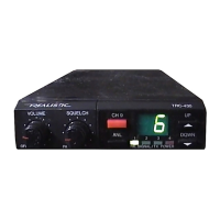
General operating characteristics including channels, frequency range, power, size, and weight.
Conditions for device performance testing, including power, temperature, and signal levels.
Instructions for removing the transceiver's top and bottom covers.
Instructions for removing the transceiver's front panel.
Diagram showing chassis layout and specific points for alignment adjustments.
Step-by-step guide for aligning PLL and carrier oscillator circuits with test equipment.
Diagram illustrating test equipment setup for PLL and carrier oscillator alignment.
Displays waveforms at IC7 pins, illustrating circuit operation and signal characteristics.
How the channel switch determines the PLL divide ratio N for frequency selection.
Example calculation for transmitting frequencies based on channel and mode settings.
Explains how the mic signal is applied and limited within the audio limiter circuit.
Describes the AMC circuit that controls maximum modulation for stability.
Explains the ALC circuit's operation for both AM and SSB modes.
Describes the noise amplifier circuit tuned to 23 MHz for noise detection and elimination.
Explains the N.B. AGC circuit's role in controlling noise and amplifier gain.
Step-by-step procedure for aligning the transmitter section with required equipment.
Diagram showing the test equipment setup for transmitter section alignment.
Step-by-step procedure for aligning the receiver section with required equipment.
Diagram illustrating the test equipment setup for receiver section alignment.
Hints for diagnosing and resolving issues when the unit fails to power on.
Hints for diagnosing and resolving issues when there is no audio output during receive.
Hints for diagnosing and resolving issues when the unit fails to transmit.
Hints for diagnosing and resolving issues related to lack of modulation during transmission.
Troubleshooting hints for SSB transmission failures.
Troubleshooting hints for AM mode modulation failures.
Hints for diagnosing and resolving issues when the noise blanker is inoperative.
Hints for diagnosing and resolving issues with the channel indicator LEDs not lighting up.
Layout diagram for the flexible channel switch printed circuit board.
Layout diagram for the noise blanker printed circuit board.
Layout diagram for the speaker jack printed circuit board.
List of capacitor part numbers, descriptions, and manufacturer codes.
List of trimmer capacitors and compound parts with their part numbers.
List of diodes with their part numbers.
List of Field Effect Transistors (FETs) with their part numbers.
List of integrated circuits with their part numbers.
List of coils and micro-inductors with their part numbers.
List of resistors with their part numbers and specifications.
List of switches with their part numbers.
List of transistors with their part numbers.
List of variable resistors with their part numbers.
List of crystals with their frequencies and part numbers.
List of miscellaneous items like speakers, jacks, and connectors.
List of check terminals and various connectors with their part numbers.
List of Printed Circuit Boards with their part numbers.
List of key components like transformers, filters, and coils with their part numbers.
List of chassis and cover parts with their part numbers.
List of mounting brackets and chassis support parts.
List of angles and brackets used for mounting PCBs and components.
List of various control knobs for functions like channel, volume, and squelch.
The front panel, LED holders, caps, and trim plates.
List of screws, studs, and plates for assembly and trim.
Various cushions, washers, and speaker netting used in assembly.
A comprehensive list of screws used for various assembly purposes.
List of nuts and springs used in the assembly.
Meter, various jacks for audio, power, microphone, and antenna connectors.
Channel switch, mode switch, and variable resistors for control.
Specific function PCBs, main PCB, and the speaker component.
Shield plates for various sections and a microphone hanger.
Washers for mounting and a lug terminal for connections.
Further list of screws used in the assembly.
Final list of screws and nuts used in the product assembly.
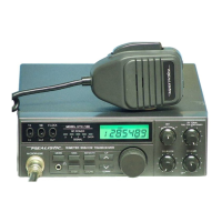
| Frequency Range | 26.965 - 27.405 MHz |
|---|---|
| Modulation | AM |
| Power Output | 4 Watts |
| Channels | 40 |
| Microphone | Dynamic |
| Antenna Impedance | 50 Ohms |
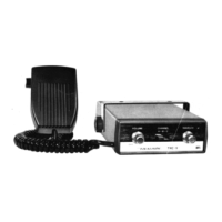
| Type | CB Radio |
| Mode | AM |