ALIGNMENT
OF
TRANSMITTER
SECTION
1.
Equipment Required:
a.
AF
Oscillator
(two
required)
f. Oscilloscope
b.
AF
VTVM
(Full scale: 1V
DC
with
RF probe)
g.
RF
VTVM
c.
DC
VOM
d. R F Power Meter
e.
50
ohm
load
and
Attenuator
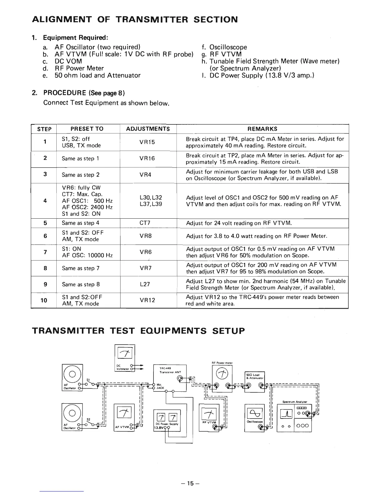
2.
PROCEDURE (See page 8)
Connect Test Equipment
as
shown below.
STEP
PRESET TO ADJUSTMENTS
1
S1,
S2
:
off
VRf5
USB,
TX
mode
2
Same
as
step 1
VR16
3
Same
as
step 2
VR4
VR6:
fully
CW
CT7: Max.
Cap.
L30,L32
4
AF
OSC1:
500
Hz
AF OSC2: 2400
Hz
L37,L39
S1
and
S2:
ON
5
Same
as
step 4
CT7
6
S1
and
S2:
OF F
VR8
AM,
TX
mode
7
S1:
ON
VR6
AF
osc:
10000
Hz
8
Same
as
step 7
VR7
9
Same
as
step 8
L27
10
S1
and
S2
:
0FF
VR12
AM,
TX
mode
h.
Tunable Field Strength Meter
(Wave
meter)
(or Spectrum Analyzer)
I.
DC
Power Supply (13.8
V/3
amp.)
REMARKS
Break
circuit
at TP4, place
DC
mA
Meter in
series.
Adjust
for
approximately
40
mA
reading. Restore circuit.
Break
circuit
at TP2, place
mA
Meter in
series.
Adjust
for
ap·
proximate~y
15
mA
reading. Restore circuit.
Adjust
for
minimum
carrier leakage
for
both USB
and
LSB
on
Oscilloscope (or Spectrum Analyzer,
if
available).
Adjust level
of
OSC1
and OSC2
for
500
mV
reading on
AF
VTVM
and
then adjust coils
for
max. reading on R F
VTVM.
Adjust
for
24
volt
reading on R F
VTVM.
Adjust
for
3.8
to
4.0
watt
reading on R F Power Meter.
Adjust
output
of
OSC1
for
0.5
mV
reading on
AF
VTVM
then adjust
VR6
for
50%
modulation on Scope.
Adjust
output
of
OSC1
for
200
mV
reading on
AF
VTVM
then adjust
VR7
for
95
to
98% modulation on Scope.
Adjust L27
to
show min. 2nd harmonic (54 MHz) on Tunable
Field Strength Meter (or Spectrum Analyzer,
if
available).
Adjust
VR12
so
the TRC-449's power meter
reads
between
red
and
white
area.
TRANSMITTER
TEST
EQUIPMENTS
SETUP
AF
Oscillator
DC
Voltmeter
AF
VTVM
1 R
C·
4
49
T
rans
ceiver
AN
T
-15-
R F Po wer meter
so
n Load
&
Attenuator
o 0
000