Do you have a question about the Realistic TRC-422A and is the answer not in the manual?
Details features enhancing selectivity, noise reduction, and reception sensitivity.
Covers LED indicators, S/RF meter, and Public Address capability.
Outlines the FCC licensing process for Class D CB operation in the USA.
Information on acquiring a DOC General Radio Service license for Canada.
Emphasizes reading the manual to resolve issues before seeking service.
Lists detailed technical specifications for receiver sensitivity and transmitter output.
Provides information on Public Address, power needs, dimensions, and weight.
Describes the main controls, switches, meters, and indicators on the front panel.
Details rear panel jacks for external speakers, PA, and antenna connections.
Step-by-step instructions for setting up and operating the transceiver for receiving calls.
Guidance on transmitting, using the emergency switch, and understanding modulation.
Instructions for using the Public Address feature and monitoring modes.
Instructions on how to connect and disconnect the locking microphone plug.
Tips on using features like ANL, S/RF Meter, and external speakers.
Provides hints and best practices for courteous CB communication.
Safety and convenience considerations for mounting the transceiver in a vehicle.
Instructions for connecting the transceiver to the vehicle's 12-volt DC power system.
Guidance on connecting the antenna system to the transceiver.
Lists the standard frequencies for all 40 CB channels.
Discusses transmission line, SWR meters, and antenna matching for optimal performance.
Provides general guidelines for properly installing any mobile CB antenna.
Discusses common mounting positions like Roof, Front Cowl, Rear Deck, and Bumper.
Brief overview of common base station antenna types: Ground Plane, Coaxial, and Beam.
Explains sources of noise and how to identify and mitigate them.
Tips for reducing noise caused by the vehicle's ignition system.
Guides users through common checks for receiving and transmitting issues.
Checks for power cable, fuse, and switch settings if the transceiver is inoperative.
Warnings against internal adjustments and advice on professional servicing.
Examples of how CB radios can be used for family communication and safety.
Applications of CB radios in business, public safety, and construction industries.
Provides the detailed electronic schematic diagram of the transceiver.
Lists common 10-codes used by CB radio operators for communication.
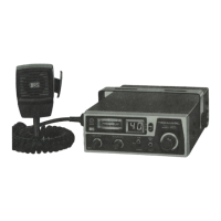
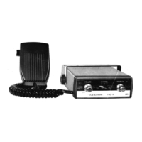
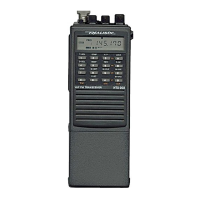
The Realistic TRC-422A is a compact 40-channel CB mobile transceiver designed for Class D operation. It is built with solid-state circuitry on rugged printed circuit boards, ensuring reliability and durability. The unit incorporates a built-in 40-channel PLL synthesizer circuit, which uses a single crystal for precise frequency control, enhancing overall reliability.
The TRC-422A functions as a two-way radio for Citizens Band (CB) mobile communication. It allows users to transmit and receive messages across 40 available CB channels. The device includes a Public Address (PA) capability, enabling it to function as a PA system when an external speaker is connected. An external speaker can also be connected for remote monitoring of incoming signals, automatically disconnecting the internal speaker.
The transceiver features a bright red LED channel indicator that displays the currently selected channel. For quick access to emergency or highway information, an Emergency Switch allows instant selection of Channel 9 (emergency communications) or Channel 19 (highway information). The unit also includes a switchable Automatic Noise Limiter (ANL) to reduce impulse-type noise during reception.
A unique Hysteresis-type Squelch circuit automatically compensates for signal fading, preventing "chopping" of messages during reception. This advanced squelch system ensures that once a signal opens the squelch, it remains open even if the signal strength fluctuates, providing clearer reception of weak or fading signals. The SQUELCH control allows users to eliminate annoying background noise between messages, keeping the radio silent until an audible message is received.
The TRC-422A is equipped with a Signal Strength/RF Output Power Meter, which provides a relative indication of RF output power during transmission and the strength of incoming signals during reception. A Modulation LED lights up during transmission and flashes with modulation, with its brilliance indicating the degree of voice modulation, reaching maximum brilliance at 100% modulation.
The device operates on any 12-volt DC system, supporting both positive and negative grounds. It comes with a dynamic communications microphone featuring a locking connector to prevent accidental disconnection. The VOLUME On/OFF Switch controls power to the transceiver and adjusts the sound level. The Channel Selector allows users to choose any of the 40 available channels. A three-way CB-PA-MONitor switch selects the desired mode of operation: CB for standard communication, PA for public address, and MONitor for monitoring CB calls through the PA speaker while in PA mode.
Before transmitting, users must have an FCC Class D Citizens Radio Service License (U.S.A.) or a Department of Communications (D.O.C.) General Radio Service License (Canada). The manual provides instructions for obtaining these licenses.
For receiving, users must ensure 12-volt power is applied, an antenna is attached, and the microphone is connected. The CB-PA-MON switch should be set to CB, and the Emergency Switch to the center position. The SQUELCH control should be set to its maximum counterclockwise position initially. Power is turned on by rotating the VOLUME control clockwise, and the desired channel is selected using the Channel Selector. VOLUME is adjusted for listening, and SQUELCH is then adjusted clockwise until background noise stops.
To transmit, users select the desired channel, press the push-to-talk button on the microphone, and speak in a normal voice about 2-3 inches (5-7.5 cm) from the microphone. Releasing the button returns the unit to receive mode. The microphone plug must be firmly connected to avoid issues like squeal or feedback. Shouting into the microphone is unnecessary as an internal circuit automatically sets the mic signal for maximum modulation.
The transceiver can be mounted under the dashboard, away from the heater or air conditioning airflow. The mounting bracket serves as a template for drilling holes. Power connection involves connecting the red wire to the positive terminal and the black wire to the negative terminal of a 12-volt DC source. An auto accessory plug can be used for the cigarette lighter, but direct connection to the ignition switch's accessory terminal is recommended for security and to prevent unintentional power-on.
The antenna system is crucial for optimal performance. A 50-ohm coaxial cable (RG-58/U for lengths under 100', RG-8/U for longer) should be used, keeping the length to a minimum. An SWR (Standing Wave Ratio) Meter is recommended to gauge antenna system efficiency. Mobile antennas should be mounted as far as possible from the main bulk of the vehicle and noise sources, and as high as possible, maintaining a vertical orientation. For boats, a metal hull or a tin-foil/copper sheeting ground of at least 12 square feet (1 m²) is required.
The manual discusses various mobile antenna types and mounting positions:
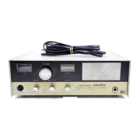
For base station operation, the transceiver can be used with a 120-volt AC/12-volt DC power supply. Three basic types of base antennas are mentioned:
All antenna systems should be adequately grounded, and a lightning arrestor is recommended.
Mobile operation can introduce noise interference, primarily from external sources like the vehicle's ignition system, generator/alternator, regulator, gauges, and static discharge. The ANL circuit helps with low-level impulse noise, but persistent loud noise requires addressing the source. A simple test involves turning off the ignition but keeping accessories on (ACC) to see if the noise disappears, indicating an ignition system source.
To reduce ignition noise, users should use "radio suppression type" high voltage ignition wire, inspect connections, and replace spark plugs with suppressor resistors if necessary. Bypass capacitors can reduce noise from other electrical systems.
The TRC-422A is built to quality standards and requires reasonable care, avoiding severe shock, dirt, or moisture. If problems arise, users should first check:
Users are warned not to open the transceiver or attempt internal adjustments or modifications, as these can lead to illegal operation and serious consequences. Any internal adjustments must be made by a person holding an FCC 1st or 2nd Class Radio Operator's License. If self-checks fail, the unit should be serviced by a qualified radio technician or returned to the store of purchase.
The manual also includes a 10-code list for faster and clearer communication in noisy environments. A 90-day limited warranty covers defects, requiring the sales slip as proof of purchase for repair at any Radio Shack store. The warranty does not cover transportation costs, misuse, or accidental damage.
| Frequency Range | 26.965 - 27.405 MHz |
|---|---|
| Modulation | AM |
| Power Output | 4 Watts |
| Channels | 40 |
| Microphone | Dynamic |
| Power Supply | 12V DC |