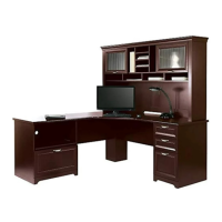
Do you have a question about the realspace Magellan Series and is the answer not in the manual?
Warnings cover child climbing, overloading, TV placement, and improper moving.
Information on product care, weight limits, and customer service contact details.
Instructions for correctly installing cam locks and pins for secure assembly.
Guide to separating inner and outer rails of the ball bearing slide mechanism.
Attaching slide rails (O1) to panel B using screws (J, L4) and dowels (K).
Attaching slide rails (O1) to panel C using screws (J, L4) and dowels (K).
Connecting brace pieces (F, F1, G, H, D) using dowels (K), screws (J, L5), and brackets (M).
Connecting side panels (D, G, H, F1) to the base structure using cam locks (I).
Connecting panels C, D, G, H, B, F1 to the main frame using cam locks (I). Requires assistant.
Attaching drawer slide supports (D, F) to panels C and B using cam locks (I) and screws (L5).
Securing the top panel (A) to the main frame using cam locks (I) and screws (J).
Securing the back panel (E) and attaching feet (N) using screws (L2, L4). Requires assistant.
Installing safety belt (R) to the top of the unit using screws (L7) and washers (T).
Assembling drawer fronts (D3) with handles (D6) using screws (A1, L5, L3) and rails (C4).
Attaching inner drawer slides (O2) to drawer side panels (D1, D2) using screws (L4).
Constructing drawer boxes by joining sides (D1, D2), back (D4), front (D3), and bottom (D5) using screws (L4, L6) and rails (A1).
Installing file hanger rails (C1, C2, C3) and drawer support rails (C4) into the drawer boxes.
Step-by-step instructions on how to safely remove drawers from the cabinet.
Instructions for installing anti-tip hardware to secure the furniture to the wall.
Details on what the 5-year warranty covers and common exclusions.
Requirement for proof of purchase for warranty claims and how to make a claim.
Warranty limitations, disclaimers, and geographic applicability.
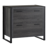
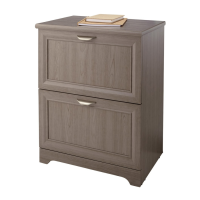
| Product Line | Magellan Series |
|---|---|
| Category | Indoor Furnishing |
| Assembly Required | Yes |
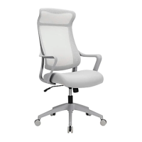
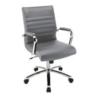
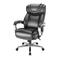
| Product Type | Office Chair |
| Material | Metal |
| Chair Material | Mesh |
| Dimensions | Various (depending on specific model) |
| Weight Capacity | Various (depending on specific model, typically 250-400 lbs) |
| Adjustability | Various (depending on specific model, e.g., Height, Tilt, Lumbar Support, Armrests) |
| Style | Various (depending on specific model, e.g., Executive, Task, Ergonomic) |