RTL8773E Motherboard User Guide
15
·Copyright 2019 Realtek Semiconductor Corporation.
All Rights Reserved.
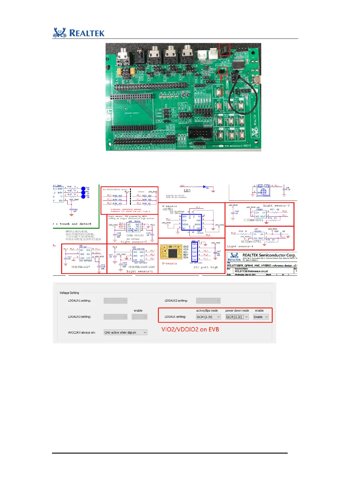
4. In application case, as G-sensor/P-sensor/Light sensor is powered by LDO_HV33 in
reference design, please make sure LDO_AUX is configured to be 3.3V.
2.2.3 Debug Interface
2.2.3.1Download
To download and debug APP program, 2 different cases are as follows:
1. J-Link is connected to corresponding SWD interface on motherboard as shown as follows.
Pay special attention to the consistency of working voltage between J-Link and Motherboard.
Keep VCC pin of J-Link floating if it is internal powered. It is suggested to pull off internal
 Loading...