RTL8773E Motherboard User Guide
17
·Copyright 2019 Realtek Semiconductor Corporation.
All Rights Reserved.
Figure 2-4 MPPG tool downloading connection
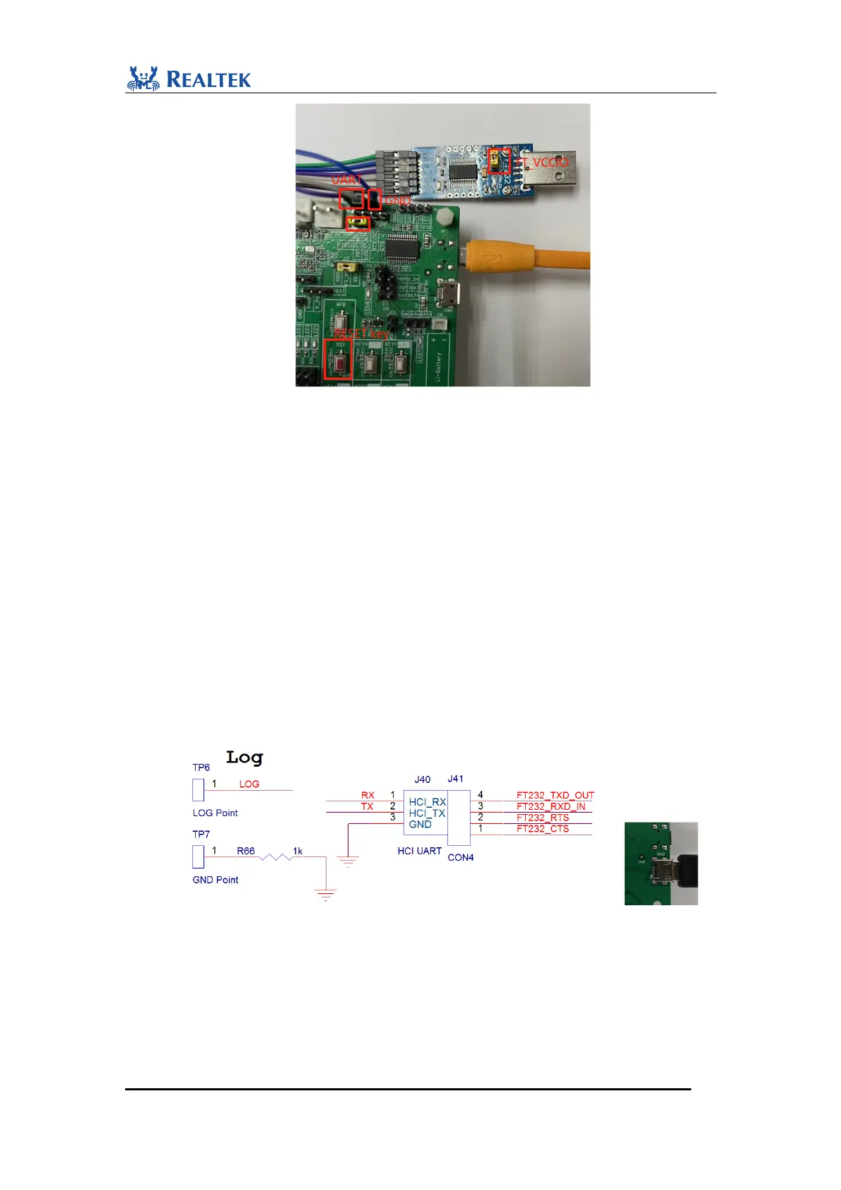
2.2.3.2LOG
In boot code, M2_0 is configured to transmit asynchronous data output as debugging
log information in UART protocol.
To use FT232 on EVB for log:
i. Firstly, please make sure pull off all the jumpers between J40 and J41.
ii. Connect J33.2 FT_VIO to J33.3 VIO2 (1.8V by default, VDDIO1/LDO_AUX in
spec) to guarantee the voltage consistency.
iii. Check bottom side of Evaluation board to confirm whether built-in FT232 chip is
mounted as shown as follows. If yes, you can use the USB connector CON3 on the
bottom side for monitoring log. Connect TP6 and J41.3, and connect CON3 to PC
as USB to UART input.
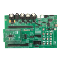
Figure 2-5 Connection for USB to UART converter
Similarly, you can use an external FT232 board to receive log.
i. Firstly, please make sure pull off the jumpers between J40 and J41.
ii. Since LOG pin (P2_0) of 8773E is in power domain VDDIO1 (LDO_AUX) which
is 1.8v by default and is marked as VDDIO2 on EVB motherboard. The jumper of
VCCIO on the external FT232 board must be pulled off and connected to VDDIO2
 Loading...