RTL8773E Motherboard User Guide
20
·Copyright 2019 Realtek Semiconductor Corporation.
All Rights Reserved.
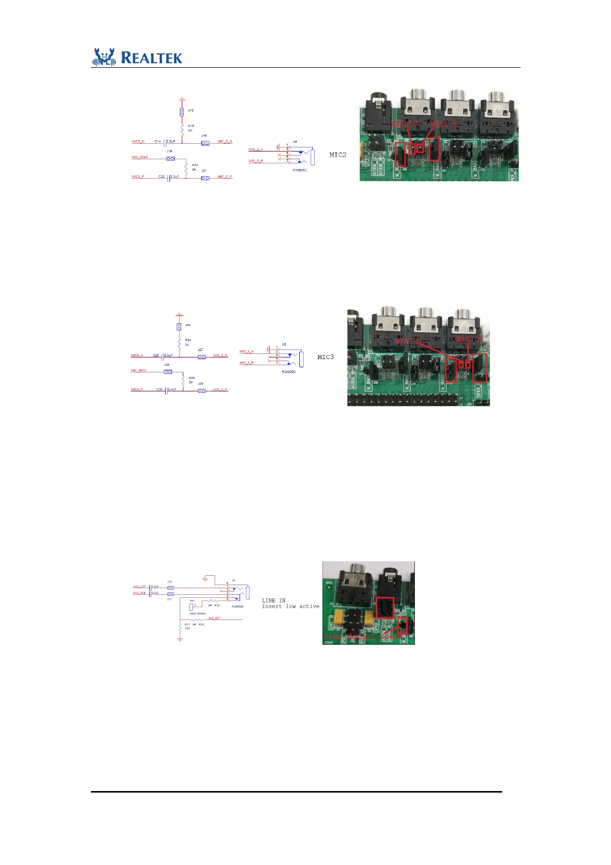
Figure 2-9 MIC2 connections for condenser microphone
MIC3 jack is used for microphone input. When used as electret condenser microphone
input, follow the steps:
1) Short J26 and J28.
2) Connect J29.1 with term 1(+) of microphone.
3) Connect J27.1 with term 2(-) of microphone as shown below. MIC3 interface begins to
sample voice signal through external microphone.
Figure 2-10 MIC3 connections for condenser microphone
For MEMS microphone application, use mic_bias for MEMS mic’s power supply, and
connect MIC+ to output of mems microphone as single-end input.
When U4 is used as aux line input, follow the steps:
1) Short J10.
2) Short J11.
3) Weld 0ohm resistor on position of R16 and R15. Connect TP1 to LDO_AUX2. When
inserting an aux line to Line-in jack, the voltage level of signal INS_DET goes down, which
means detection of aux line insertion is active-low.
Figure 2-11 Aux line in
Headphone jack is intended for headphone output. Connection of jumpers depends on
application. The following are the steps to perform single-end application:
1) Disconnect J12, J8 and J13. Connect J9.1 with J9.2. In this way, U3.1 is connected to ground.
SPKL_P and SPKR_P are transmitted through tantalum capacitors C9 and C6 to
daughterboard.
The following are the steps to perform cap-less application:
 Loading...